GENERAL
mini HE --- Installation & Servicing
6
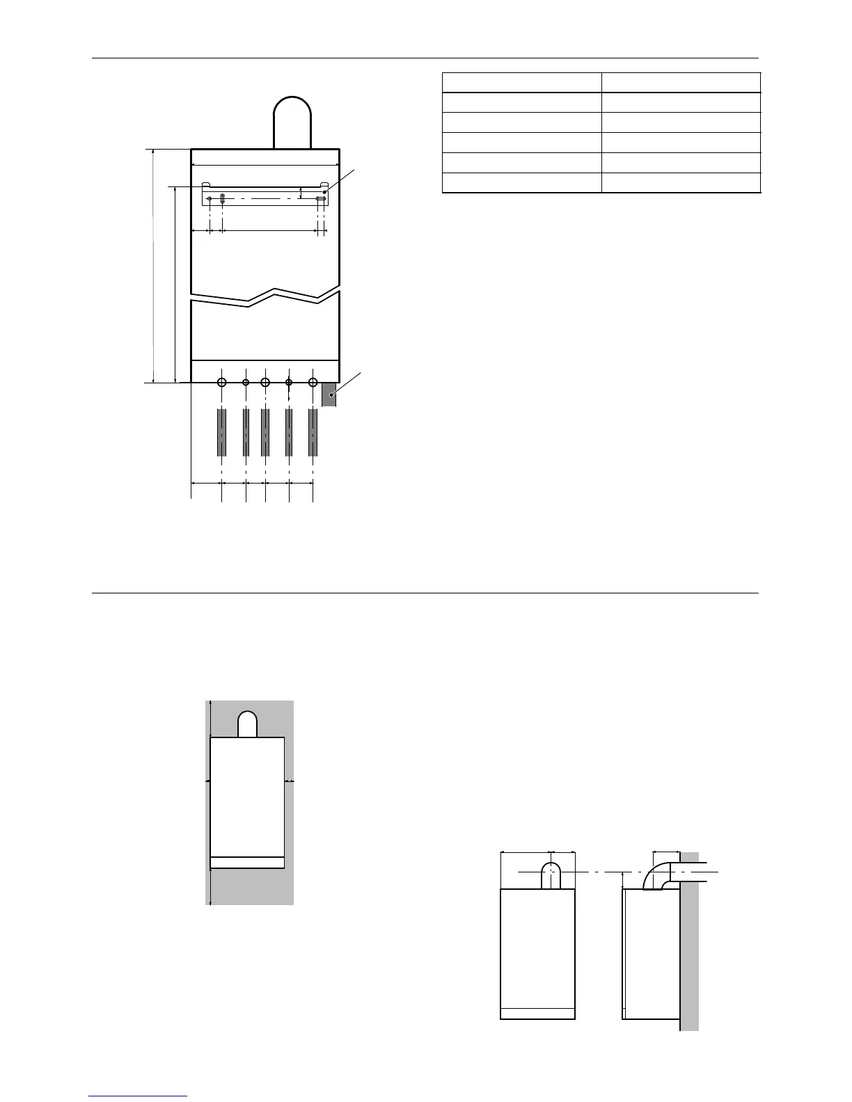
1 BOILER WATER CONNECTION
400
803
700
35
257
16
31
50
65 (2 9/16”)
83 (3 1/4”)
65 (2 9/16”)
52 (2”)
64 (2 1/2”)
CH return
CH flow
DHW cold inlet *
Gas inlet
DHW hot outlet *
Wall
mounting
Plate
Condensate
drain
connection
area
Pipe size O.D. mm
CH flow 22
CH return 22
Gas inlet 22
DHW cold inlet 15
DHW hot outlet 15
2 BOILER CLEARANCES
All dimensions in mm (in.)
The following minimum clearances must be maintained for
operation and servicing. Additional space will be required for
installation, depending upon site conditions.
25 (1”) 50 (2”)
200 (7 7/8”)
200 (7 7/8”)
Bottom clearance
The bottom clearance, after installation, can be reduced to
20mm. However, 200mm must be available for servicing.
Front clearance
The minimum front clearance when built into a cupboard is
50mm (2”) from the cupboard door. However 450mm
(17 3/4”) overall clearance is still required, with the cupboard
door open, to allow for servicing.
Side and Rear Flue
a. Provided that the flue hole is cut accurately, e.g. with a core
drill, the flue can be installed from inside the building where
wall thickness does not exceed 600 mm (24”).
Where the space into which the boiler is going to be installed
is less than the length of flue required the flue must be fitted
from the outside.
installation from inside ONLY
b. If a core boring tool is to be used inside the building the
space in which the boiler is to be installed must be at least
wide enough to accommodate the tool.
190 (7 1/2”)
95 ()
273 (10 3/4”) 127 (5”)