INSTALLATION
14
mini HE --- Installation & Servicing
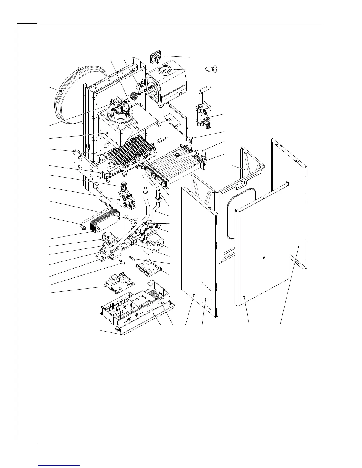
8 BOILER ASSEMBLY ---
Exploded View
17
38
1
11
27
7
10
18
8
40
23 21
4
24
16
14
13
32
28
26
12
29
30
31
15
33
34
36
35
9
6
37
20
39
1922
2
41
3
5
25
1 Air pressure switch
2 Recuperator
3 Condensate trap
4 Overheat thermostat
5 Condensing to main heat
exchanger connection pipe
6 Primary heat exchanger
7 Inner case cover
8 Flame detection electrode
9 Ignition electrodes
10 Heat exchanger return pipe
11 Auto air vent
12 Main circuit drainage cock
13 Pump
14 DHW flow switch
15 DHW Thermistor
16 Ignition pcb
17 Right hand panel
18 Boiler front panel
19 Appliance data badge (inside)
20 Left hand panel
21 CH circuit pressure gauge
22 Model identification & instructions
23 Control panel door
24 Main control pcb
25 CH Thermistor
26 CH flow switch
27 Heat exchanger flow pipe
28 Return manifold
29 3 way diverter valve
30 DHW heat exchanger
31 Bypass pipe
32 3 bar pressure relief valve
33 Gas valve
34 Gas valve outlet pipe
35 Injector manifold
36 Burner
37 Flue hood
38 Fan
39 Expansion vessel
40 Venturi
41 Flue thermostst
INSTALLATION
 Loading...