SERVICING
mini HE --- Installation & Servicing36
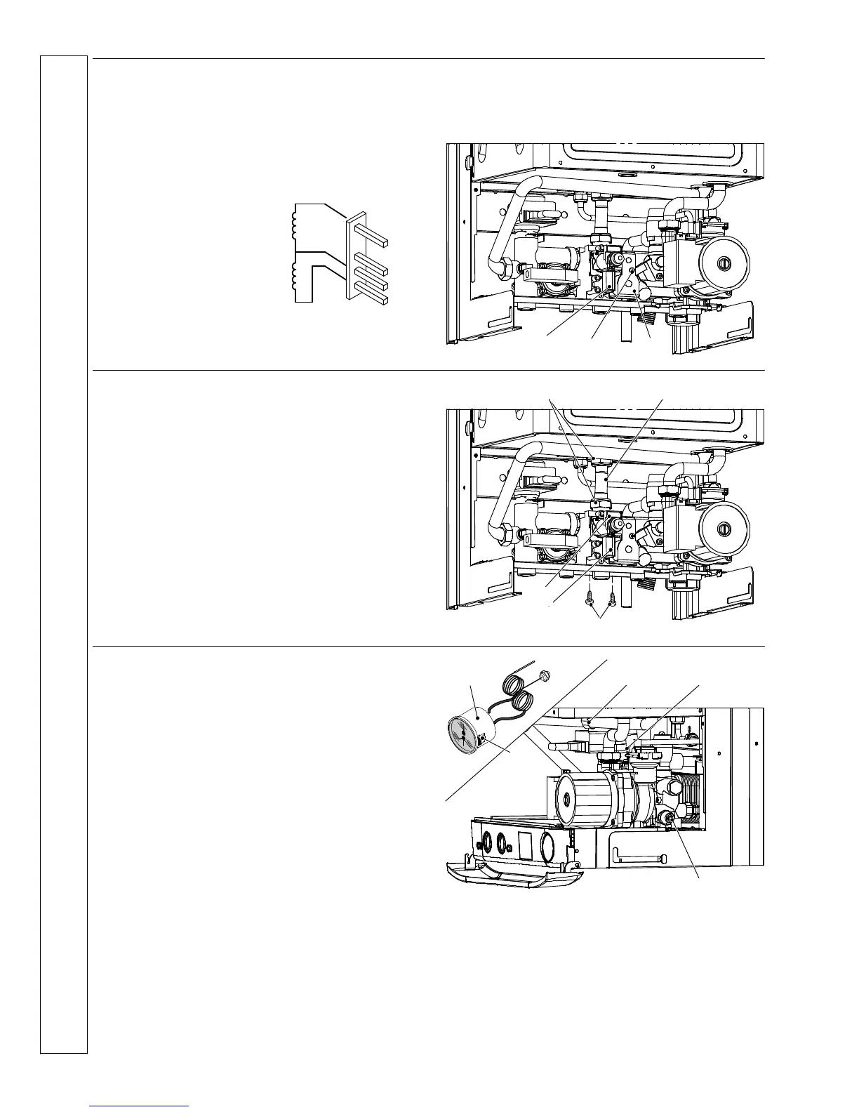
47 GAS VALVE ON---OFF OPERATOR
COILS REPLACEMENT
Check
1 Disconnect the electrical supply.
2 Remove the front casing panel.
3 Disconnect the connector A and check the electrical
resistance of the coils referring to the following diagram
Lower on---off operator
approx. 920 W*
Upper on---off operator
approx. 6 400 W*
* at ambient temperature.
4 If the resistance of either of the coils is different from the
value stated by ±10% or greater, replace the unit as
described below.
Replacement
5 Remove the screw B, withdraw the coils unit C.
6 Replace it and re---assemble in reverse order.
A
B
C
48 GAS VALVE REPLACEMENT
1 Turn off the gas supply at the gas service cock and
disconnect the electricity supply.
2 Remove the front casing panel (refer to frame 34).
3 Disconnect the connectors A and B.
4 Disconnect the earth wiring from the gas valve.
5 Unscrew the connectors C and remove the pipe D
6 Unscrew the inlet connector.
7 Unscrew the screws E and remove the valve.
8 Fit the new gas valve in reverse order ensuring new
gaskets are fitted and check for gas soundness.
9 Check the operation of the boiler.
B
C D
E
A
49 WATER TEMPERATURE---PRESSURE
GAUGE REPLACEMENT
1 Disconnect the electrical supply.
2 Remove the front and right hand side casing panels (refer
to frame 34).
3 Release system pressure by opening the main circuit
drainage cock A
Do not release CH pressure using the pressure relief
valve. It may cause debris within the system to foul
the valve.
4 Remove the fork B and the probe holder spring C.
5 Pull out the control panel (see frame 22).
6 Squeeze the tabs D to release the temperature---pressure
gauge E and remove it.
7 Re ---assemble in reverse order.
C B
E
D
A
SERVICING