SERVICING
mini HE --- Installation & Servicing 41
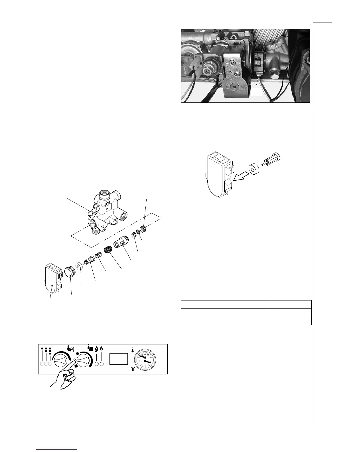
59 DHW FLOW SWITCH REPLACEMENT
1 Disconnect the electrical supply.
2 Remove the front panel of the case (refer to frame 34).
3 Disconnect the connector A and remove the sensor by
pulling it towards the front of the boiler (the sensor is held
in place by means of a spring).
4 Replace the sensor and re---assemble in reverse order
A
60 DHW FILTER AND FLOW LIMITER
REPLACEMENT
1 Disconnect the electrical supply.
2 Remove the front panel of the case and empty the DHW
circuit.
3 Remove the flow switch A (see frame 59).
4 Remove the gas valve (see frame 48).
5 Unscrew the plug B and extract the flow switch group.
6 To remove the filter C from the flow switch group separate
the body D from the plug B by unscrewing it.
7 Re ---assemble in reverse order.
A --- flow switch
B --- plug
C --- filter
D --- body
Magnetic ring
Float
Spring
Spring seat
Flow limiter
Threaded ringThreaded ring
Return manifold
Attention: the magnetic ring has a magnetic polarity and
must be correctly coupled with the spindle of the float.
To determine the correct orientation of the ring proceed as
follows:
1 Set the function selector of the boiler in stand---by mode.
2 Restore the mains electricity supply to the boiler.
Warning --- ensure that all the electric parts and wiring
are dry and do not touch other electric parts during
the following operations.
3 Hold the flow switch sensor and bring the ring in contact
with the sensor as illustrated in the following
drawing.
4 Observe if the lamp fitted in the sensor body is lit. If not
reverse the ring and repeat the previous operation.
5 Fit the ring on the spindle of the float in the way that lights
the lamp. Ensure filter is correctly positioned and that plug
“B” and the threaded ring are screwed tight into the body
“D”.
6 Isolate the boiler from the mains electricity supply and
reassemble the parts following the removing sequence in
reverse order.
Flow limiter
The mini HE C24 model is factory fitted with a 10 litre/min.
flow limiter.
The mini HE C28 model is factory fitted with a 12 litre/min.
flow limiter.
Table 8
Nominal flow rate (litres/min)
Colour
10 Yellow
12 Brown
1 Disconnect the electrical supply.
2 Remove the front panel of the case and empty the DHW
circuit.
3 Remove the flow switch A (see frame 59).
4 Remove the gas valve (see frame 48).
5 Remove the flow switch group (see frame 60 above)
6 Unscrew the threaded ring and extract the flow limiter.
7 Fit the correct colour coded limiter (see Table 8 above)
and screw the threaded ring tight into the body ’D’.
8 Re ---assemble in reverse order.
SERVICING
 Loading...