SERVICING
mini HE --- Installation & Servicing 45
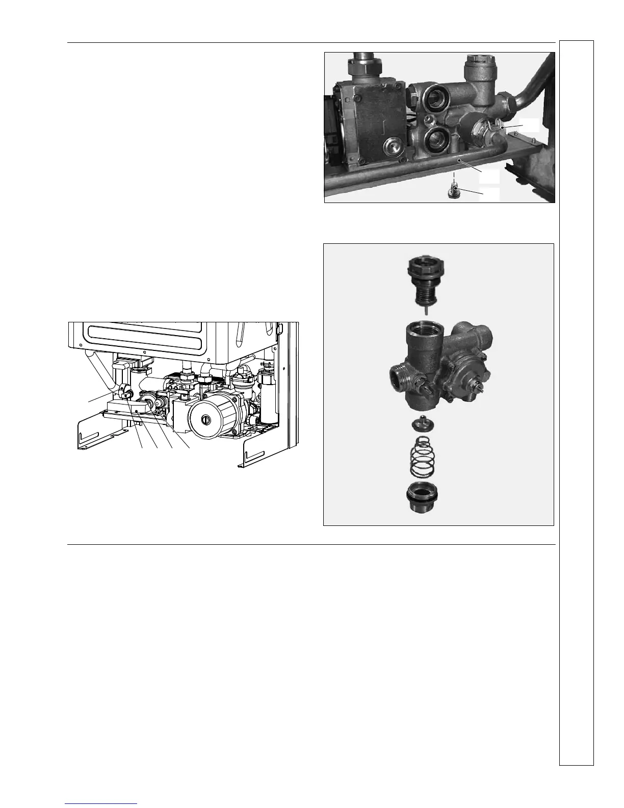
65 DIVERTER VALVE INTERNAL PARTS
REPLACEMENT
1 Disconnect the electrical supply.
2 Remove front and left hand casing panels (refer to frame
34).
3 Close the isolating cocks of the CH circuit and DHW
supply at the bottom of the boiler.
4 Release system pressure by opening the main circuit
drainage cock.
Do not release CH pressure using the pressure relief
valve. It may cause debris within the system to foul
the valve.
5 Release the pressure of the DHW circuit by opening a hot
tap.
6 Remove the diverter valve actuator (see frame 64).
7 Remove the fork D and remove the primary circuit flow
switch E.
8 Disconnect both CH and DHW thermistors F.
9 Unscrew the connector G, disconnect the CH flow and
DHW outlet isolator valves.
DE
G
F F
10 Remove the DHW heat exchanger (see frame 63).
11 Remove the fork H and move away the pipe I.
12 Unscrew the screw J and remove the diverter (flow)
group.
H
I
J
(rear view)
13 Refer to the following exploded view to remove the
internal parts of the three way diverter valve.
14 Re---assemble in reverse order.
66 PROGRAMMER REPLACEMENT
(if fitted)
1 Disconnect the electrical supply.
2 Gain access to the main control p.c.b. (steps 1 to 4 of
frame 55).
3 Disconnect the wiring at the programmer.
4 Squeeze the hooks that hold the programmer on the
control panel fascia and withdraw the faulty programmer.
5 Re ---assemble in reverse order.
When reassembling the new programmer, refer to the wiring
diagram in frame 23 for the correct wiring connection.
6 Replace the panels and check the operation of the new
programmer.
SERVICING