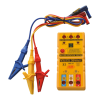
If the counter clockwise indicator is lit, alternate
the connection two of the three alligator clips.
When the clockwise indicator is lit and the
power source terminals are connected by the
RED, YELLOW and BLUE alligator clips, the
phase sequence indicators (R, S and T) shall
be lit respectively.
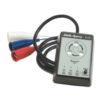
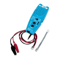
Operation of Motor Rotation Tester :
(1) Make sure there is no voltage present.
(2) Connect the test leads to motor input
terminals by L1-L2-L3, and press the power
button (Fig1). The power indicator green
lamp is lit. (If the clockwise or counter
clockwise red indicator is lit before rotating
the motor shaft, it means voltage is present.
Stop measuring. Take off the test leads and
turn off the external power). Rotate the
motor shaft clockwise. If the clockwise
indicator is lit, it means there is a 3-phase
motor connection to the power supply by L1-
L2-L3. The 3-phase motor should be rotated
clockwise.
(3) Connect the leads to 3-phase motor by
L1-L2-L3, and press the power button. The
power indicator green lamp is lit.
2
-5-
2