22
classic HE P - Installation & Servicing
INSTALLATION
SIDE FLUE OUTLET
30
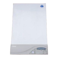
FITTING THE KIT
1. Fit the inner flue extension duct onto
the inner flue duct.
2. Fit the outer flue extension duct onto
the outer air duct.
3. Repeat steps 1 and 2 if a second flue
extension is required.
4. Measure and mark the flue length
required onto the flue, measuring from
the ring near the terminal. (Refer to Frames
10 and 23 for the detail of flue length
calculation). Ensure the support clip is in position
to facilitate cutting.
5. To ensure a square cut, mark the flue all the way
around.
6. De-burr the cut edges.
29
FLUE EXTENSION DUCTS - continued
28
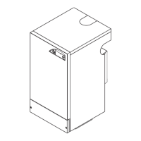
FLUE EXTENSION DUCTS - For flue lengths greater than 705mm rear flue or 775mm side flue
Flue duct support
Wall plugs - 2 off
Washers - 2 off
Extension duct & clamp
1.0m (39") long
Support fixing screws - 2 off
Clamp screws - 2 off
mxhe7656
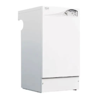
Flue length Accessories Product No.
R or L
Up to 775 B Pack 1 off see Frame 10
775 to 1680 B Pack 1 off + D Pack, 1 off see Frame 10
1680 to 2585 B Pack 1 off + D Pack, 2 off see Frame 10
2585 to 3000 B Pack 1 off + D Pack, 3 off see Frame 10
Flue extensions of greater length than 1m (39") should be
supported with the bracket provided, suitable adjusted. Refer to
Frame 28.
Measure from
this
RING
1
2
cla7845
202107-6.pmd 20/02/2008, 13:5722
 Loading...