classic HE P - Installation & Servicing
29
INSTALLATION
Flue protection
thermostat
Thermostat
sensor
Limit
thermostat
cla7677
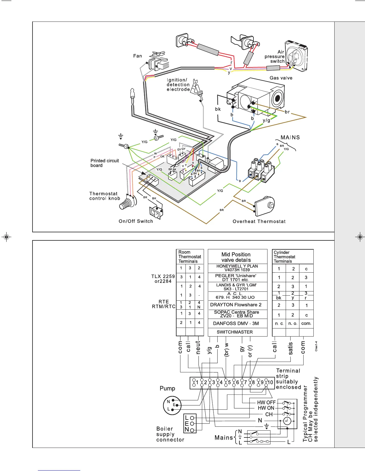
Notes.
1. Some earth wires are omitted for
clarity. Ensure proper earth continuity
when wiring.
2. Numbering of terminals on
thermostats is specific to the
manufacturer.
3. This is a fully controlled system - set
the boiler thermostat to maximum.
4. Switchmaster 'Midi' is similar in
operation but the wiring differs slightly
- see the manufacturer's literature.
43
PICTORIAL WIRING
44
MID POSITION VALVE
Pumped only
LEGEND
b-blue
bk - black
br - brown
gy - grey
or - orange
pk - pink
r-red
v-violet
w-white
y-yellow
y/g - yellow/green
LEGEND
b-blue
bk - black
br - brown
gy - grey
or - orange
pk - pink
r-red
v-violet
w-white
y-yellow
y/g - yellow/green
INSTALLATION
202107-6.pmd 20/02/2008, 13:5729