80
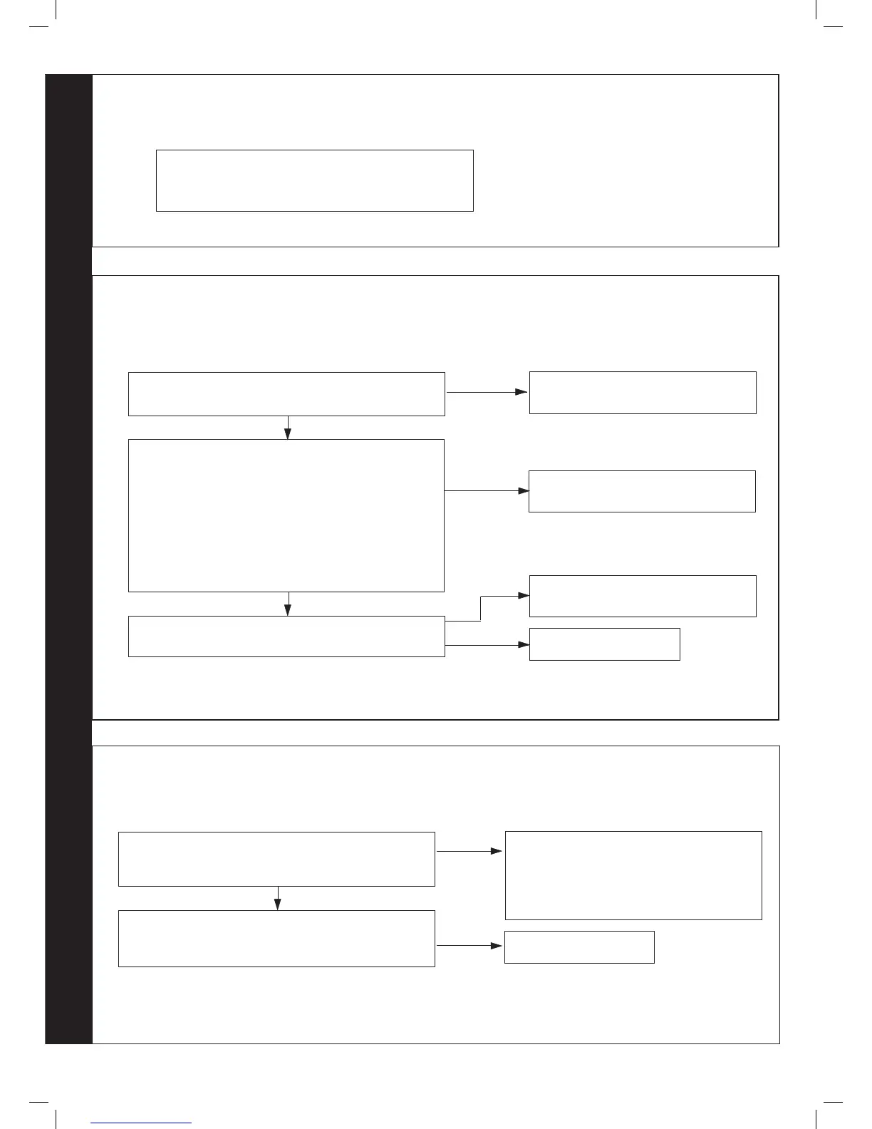
ALTERNATING ‘F’ AND ‘4’ - FLOW THERMISTOR FAULT
Disconnect the wiring from the Flow Thermistor
Check the resistance using a suitable multimeter connected
across the Thermistor’s terminal pins.
At 25
o
C expect 9,700 - 10,300 Ohms
At 60
o
C expect 2,400 - 2,600 Ohms
At 85
o
C expect 1,000 - 1,100 Ohms
Is the Thermistor value correct?
YES
Is the wiring securely connected to the low voltage 6 way
connector at the front left hand side of the PCB?
YES
Replace PCB
Fit a new Thermistor
NO
Securely connect the wiring to the PCB
Is the wiring securely connected to the Flow Thermistor
(located in the top of the Heat Exchanger?)
YES
NO
Securely connect the wiring to the Flow
Thermistor
NO
79
ALTERNATING ‘F’ AND ‘9’ - PCB FAULT
Replace PCB -
Ensure that the BCC (boiler chip card - small plastic part) is
tted to the PCB otherwise replace PCB.
81
ALTERNATING ‘c’ AND ‘2’ - BCC FAULT (BOILER CHIP CARD)
Is the correct BCC for the boiler securely inserted into the
slot at the front left of the PCB?
(identied by the label on the BCC)
YES
NO
Securely insert the correct BCC for the boiler
into the PCB and after switching power on and
‘c0’ being shown, restart boiler.
Note. Ensure the correct orientation of BCC by
placing “TOP” side up.
Replace the BCC with a new BCC (that is correct for the
boiler). After switching power on and ‘c0’ being shown,
press restart. Is ‘c2’ still shown?
Replace PCB
YES
RESTART PROCEDURE - To restart boiler, turn mode knob to restart position and immediately turn knob back to required setting.
 Loading...