1 98765432 10
11
12
N L 1 2 3 4
OFF ON OFF ON
HW CH
1 2 3 4
Room ThermostatCentral Heating Control
L
N
E
Mains Supply
Fed Via Double
Pole Isolator
230 VAC ~ 5 Amps
Danfoss
WB12
Wiring
Centre
HTG
VALVE
HW
VALVE
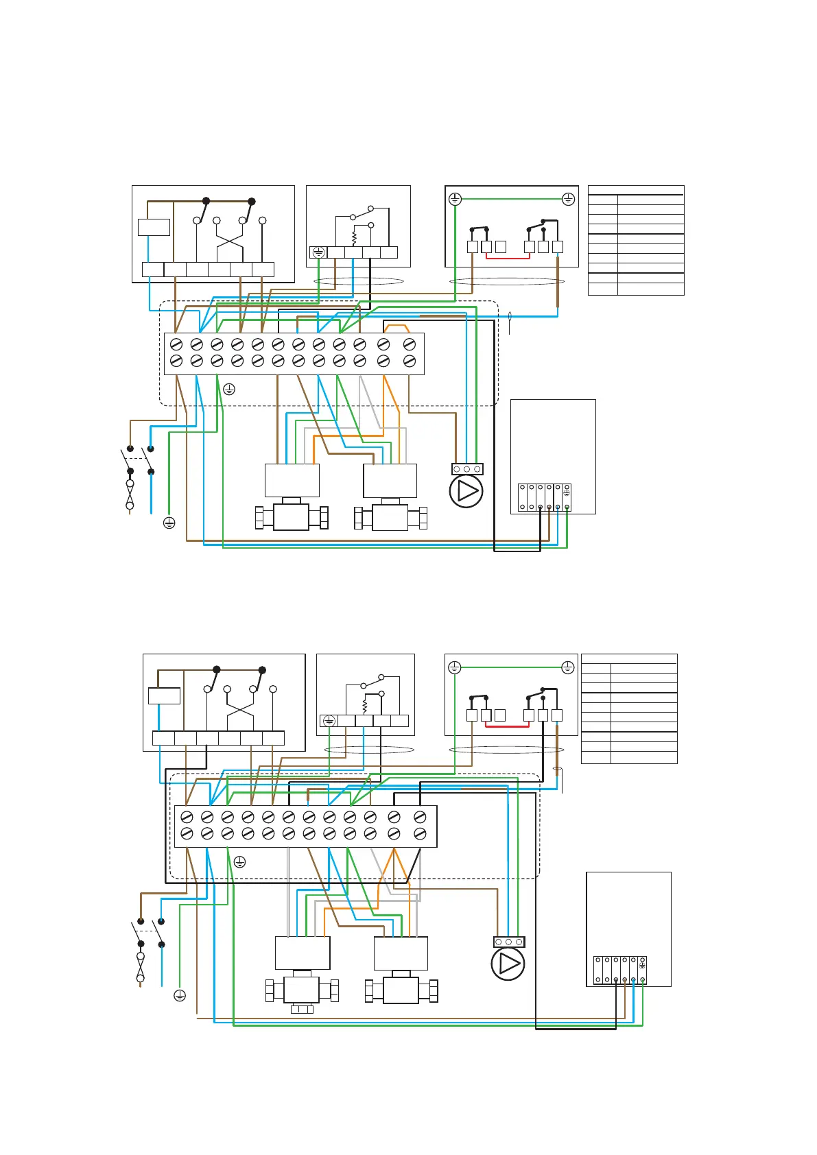
Typical schematic wiring diagram for an unvented installation
The electrical installation must
comply with IEE requirements.
For electrical installation
refer to BS7671
Note: Do not attempt
the electrical work unless
you are competent to carry
out to the above standard
BlueBl
BrownBr
Green
Grey
Green / Yellow
G
Gr
G/Y
WIRE COLOUR LEGEND
Black
Orange
Yellow
White
Red
B
Or
Y
Wh
R
Br Bl G/Y Br Br Bl G/Y
Or
Gr
5 Amps
Br Bl
G/Y
Br Br B
*Br
Bl
G/Y
Br
B
Bl Br Br Br
Br Bl B
G/Y
* Blue core used
from standard 3 core
flex please ensure you
use brown sleeving at
both terminating ends
to identify core potential.
4 core cable
L N
B Br Bl G/Y
Boiler
Pump
V4043A
TWO PORT
ZONE VALVE
A
B
HTG
Br Bl G/Y
OrGr
V4043A
TWO PORT
ZONE VALVE
A
B
DHW
Br Bl G/Y Or Gr
IN
L
IN
L
N
E
SL2 SL1 Mains In
L
N
E
(S-PLAN) WIRING DIAGRAM WITH TWO 2 PORT VALVES
Br Bl G/Y
B
Or
ELECTRONICS
1
C
2
1
C
2
Dual Cylinder Stat
Overheat Stat
Spade
connectors
required
for earth
connections
Control Stat
G/Y Br
R (Supplied with stat)
*BrB
4 core cable
*Ideal Logic Heat H
(without outside sensor)
*For Logic System S
ignore pump wiring
IN
L
IN
L
N
E
SL2 SL1 Mains In
1 98765432 10
11
12
N L 1 2 3 4
OFF ON OFF ON
HW CH
1 2 3 4
Room ThermostatCentral Heating Control
1
C
2
1
C
2
Dual Cylinder Stat
Overheat Stat
Spade
connectors
required
for earth
connections
Control Stat
L
N
E
Mains Supply
Fed Via Double
Pole Isolator
230 VAC ~ 5 Amps
HTG
VALVE
HW
VALVE
Typical schematic wiring diagram for an unvented installation
The electrical installation must
comply with IEE requirements.
For electrical installation
refer to BS7671
Note: Do not attempt
the electrical work unless
you are competent to carry
out to the above standard
BlueBl
BrownBr
Green
Grey
Green / Yellow
G
Gr
G/Y
WIRE COLOUR LEGEND
Black
Orange
Yellow
White
Red
B
Or
Y
Wh
R
Br Bl G/Y Wh Br BrBl G/Y
Or B
Gr Gr
5 Amps
Br Bl
G/Y
Br Br B
*Br
Bl
G/Y
Bl Br Br Br
Br Bl B
G/Y
G/Y Br
R (Supplied with stat)
*BrB
* Blue core used
from standard 3 core
flex please ensure you
use brown sleeving at
both terminating ends
to identify core potential.
4 core cable
4 core cable
L N
B Br Bl G/Y
Boiler
Pump
A
B
HTG
Wh Bl G/Y
OrGr
A
B
DHW
Br Bl G/Y Or Gr
L
N
E
(Y-PLAN) WIRING DIAGRAM WITH 3 PORT VALVE/2 PORT SAFETY VALVE
Br Bl G/Y
B
B
ELECTRONICS
V4073A
MID POSITION
ZONE VALVE
V4043A
TWO PORT
ZONE VALVE
*Ideal Logic Heat H
(without outside sensor)
*For Logic System S
ignore pump wiring