1 98765432 10
11
12
N L 1 2 3 4
OFF ON OFF ON
HW CH
1 2 3 4
Room ThermostatCentral Heating Control
L
N
E
Mains Supply
Fed Via Double
Pole Isolator
230 VAC ~ 5 Amps
Danfoss
WB12
Wiring
Centre
HTG
VALVE
HW
VALVE
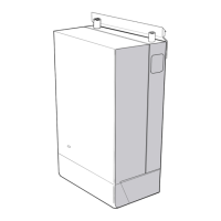
Typical schematic wiring diagram for an unvented installation
The electrical installation must
comply with IEE requirements.
For electrical installation
refer to BS7671
Note: Do not attempt
the electrical work unless
you are competent to carry
out to the above standard
BlueBl
BrownBr
Green
Grey
Green / Yellow
G
Gr
G/Y
WIRE COLOUR LEGEND
Black
Orange
Yellow
White
Red
B
Or
Y
Wh
R
Br Bl G/Y Br Br Bl G/Y
Or
Gr
5 Amps
Br Bl
G/Y
Br Br B
*Br
Bl
G/Y
Br
B
Bl Br Br Br
Br Bl B
G/Y
* Blue core used
from standard 3 core
flex please ensure you
use brown sleeving at
both terminating ends
to identify core potential.
4 core cable
L N
L
L_P
SL_B
E
N
N_P
E_P
Br Bl G/Y B Br Bl G/Y
Boiler
Pump
ISSUE No : 5
APPROVED
DRN.
DATE
07-12-10
N. Fursman
V4043A
TWO PORT
ZONE VALVE
A
B
HTG
Br Bl G/Y
OrGr
V4043A
TWO PORT
ZONE VALVE
A
B
DHW
Br Bl G/Y Or Gr
GAS BOILER
Boiler Permanent Live
Boiler Neutral
Boiler Earth
Boiler Switch Live Demand
Boiler Controlled Pump
Provide extra core
from terminal 12 to
L-P connection on
the boiler (shown
dotted) and remove
the boiler pump link
if the boiler has an
independant
pump output.
L
N
E
(S-PLAN) WIRING DIAGRAM WITH TWO 2 PORT VALVES AND BOILER CONTROLLED PUMP OVERRUN OPTION
Br Bl G/Y
B
Br
Or
ELECTRONICS
1
C
2
1
C
2
Dual Cylinder Stat
Overheat Stat
Spade
connectors
required
for earth
connections
Control Stat
G/Y Br
R (Supplied with stat)
*BrB
4 core cable
1 98765432 10
11
12
N L 1 2 3 4
OFF ON OFF ON
HW CH
1 2 3 4
Room ThermostatCentral Heating Control
1
C
2
1
C
2
Dual Cylinder Stat
Overheat Stat
Spade
connectors
required
for earth
connections
Control Stat
L
N
E
Mains Supply
Fed Via Double
Pole Isolator
230 VAC ~ 5 Amps
HTG
VALVE
HW
VALVE
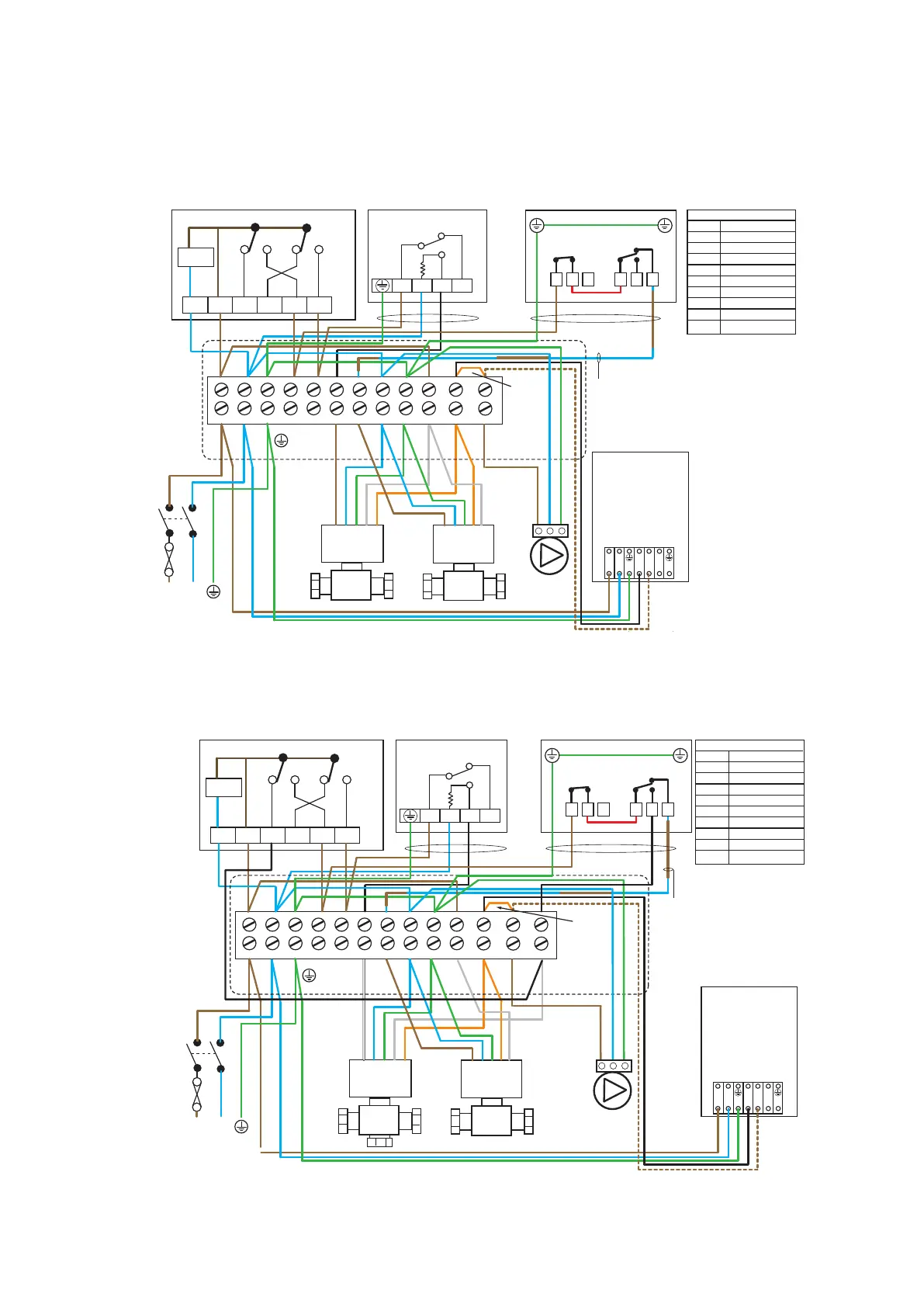
Typical schematic wiring diagram for an unvented installation
The electrical installation must
comply with IEE requirements.
For electrical installation
refer to BS7671
Note: Do not attempt
the electrical work unless
you are competent to carry
out to the above standard
BlueBl
BrownBr
Green
Grey
Green / Yellow
G
Gr
G/Y
WIRE COLOUR LEGEND
Black
Orange
Yellow
White
Red
B
Or
Y
Wh
R
Br Bl G/Y Wh Br BrBl G/Y
Or B
Gr Gr
5 Amps
Br Bl
G/Y
Br Br B
*Br
Bl
G/Y
Bl Br Br Br
Br Bl B
G/Y
G/Y Br
R (Supplied with stat)
*BrB
* Blue core used
from standard 3 core
flex please ensure you
use brown sleeving at
both terminating ends
to identify core potential.
4 core cable
4 core cable
L N
L
L_P
SL_B
E
N
N_P
E_P
Br Bl G/Y B Br Bl G/Y
Boiler
Pump
ISSUE No : 4
APPROVED
DRN.
DATE
07-12-10
N. Fursman
A
B
HTG
Wh Bl G/Y
OrGr
A
B
DHW
Br Bl G/Y Or Gr
GAS BOILER
Boiler Permanent Live
Boiler Neutral
Boiler Earth
Boiler Switch Live Demand
Boiler Controlled Pump
Provide extra core
from terminal 12 to
L-P connection on
the boiler (shown
dotted) and remove
the boiler pump link
if the boiler has an
independant
pump output.
L
N
E
(Y-PLAN) WIRING DIAGRAM WITH 3 PORT VALVE/2 PORT SAFETY VALVE AND BOILER CONTROLLED PUMP OVERRUN OPTION
Br Bl G/Y
B
B
Br
Or
ELECTRONICS
13
V4073A
MID POSITION
ZONE VALVE
V4043A
TWO PORT
ZONE VALVE