Page 10
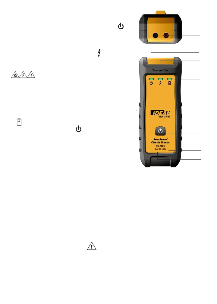
Transmitter Callout Features TR-946
1. Output Jacks – Polarized, standard banana plug type.
2. Power Indicator – When the transmitter is On, the LED
illuminates indicating that a signal is being produced.
3. Line Energized Indicator – The transmitter continuously
monitors the voltage across its output terminals. If greater than
30 volts AC or 40 volts DC is present, the LED indicator
illuminates. The transmitter also communicates the line
voltage state to the receiver. (CertainCircuit™)
WARNING
Arc Flash and Shock Hazard, Proper PPE Required. When the Line
Energized Indicator is not illuminated, check for the presence of
dangerous voltage with a measuring device to verify voltage levels
prior to working on the circuit that the transmitter leads are
connected to. Failure to comply can result in serious injury or death.
4. Low Battery Indicator – When the low battery indicator
flashes, the batteries must be replaced
5. Power Button – Depress the button to switch power
on and enable the transmit function. Depress again to
conserve battery power when not in use.
6. Operating Voltage Range – Operates on energized/
de-energized circuits from 0 to 480V AC/DC.
7. Battery Compartment – Holds (6) AA batteries.
8. Safety – Rated for use in CAT III 480V environments.
Incorporates a high-energy, fast-acting ceramic fuse.
Additional Notes
• The transmitter’s signal does not affect sensitive, electronic equipment on the circuit when placed
on the 120 volt supply.
• In a closed circuit, because the transmitter generates a small test current, its signal can be detected
upstream through the feeder panel and the distribution transformer. The strength of the signal is
reduced as it passes through the transformer in inverse proportion to the turns ratio of the
transformer.
• Can be used on GFCI protected circuits.
• Auto power off after 2 hours on the transmitter and 10 minutes on the receiver.
CAUTION
• The transmitter is rated for 0 to 480 Volts AC 50 or 60 Hz or DC. It is not compatible with
non-sinusoidal or distorted waveforms as are found at the output of variable frequency drives,
dimmer switches or in the presence of harmonically distorted waveforms.
• Connecting to these sources will damage the transmitter.
• Shipboard inverters can also cause damage to the transmitter.
1
2
4
3
5
7
6
8