7: BASIC INSTRUCTIONS
« FC4A MICROSMART USER’S MANUAL » 7-11
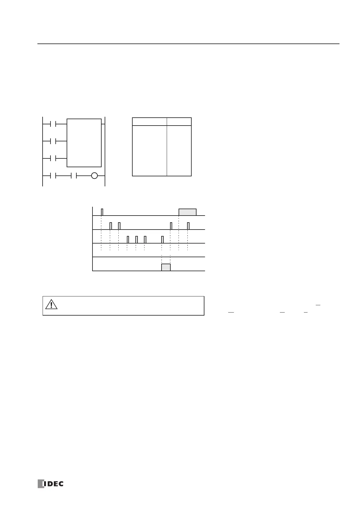
CDP (Dual-Pulse Reversible Counter)
The dual-pulse reversible counter CDP has up and down pulse inputs, so that three inputs are required. The circuit for a
dual-pulse reversible counter must be programmed in the following order: preset input, up-pulse input, down-pulse input,
the CDP instruction, and a counter number C0 through C99, followed by a counter preset value from 0 to 65535.
The preset value can be designated using a decimal constant or a data register. When a data register is used, the data of the
data register becomes the preset value.
500 500
Ladder Diagram
Preset Input I0
ON
OFF
Up Pulse I1
ON
OFF
Down Pulse I2
ON
OFF
Timing Chart
Counter C1
ON
OFF
500 501 502 501
Counter C1 Value
500 499 0 1
• • •
• • •
I0
I1
CDP C1
500
I2
Preset Input
Up Pulse
Down Pulse
I3
C1
Instruction Data
LOD
LOD
LOD
CDP
LOD
AND
OUT
I0
I1
I2
C1
500
I3
C1
Q1
Program List
• The same counter number cannot be pro-
grammed more than once.
• The preset input must be turned on initially so
that the current value returns to the preset
value.
• The preset input must be turned off before
counting may begin.
• When the up pulse and down pulses are on
simultaneously, no pulse is counted.
• The counter output is on only when the cur-
rent value is 0.
• After the current value reaches 0 (counting
down), it changes to 65535 on the next count
down.
• After the current value reaches 65535 (count-
ing up), it changes to 0 on the next count up.
• When power is off, the counter’s current
value is held, and can also be designated as
“clear” type counters using the Function Area
Settings (see page 5-4).
• Counter preset and current values can be
changed using WindLDR without download-
ing the entire program to the CPU again.
From the WindLDR menu bar, select Online >
M
onitor, then select Online > Point Write.
To change a counter preset value, specify the
counter number with a capital C and a new
preset value. To change a counter current
value, specify the counter number with a
small c and a new current value while the
counter preset input is off.
• When the preset or current value is changed
during counter operation, the change
becomes effective immediately.
• For the data movement when changing, con-
firming, and clearing preset values, see page
7-13. Preset values can also be changed and
changed preset values can be confirmed using
the HMI module. See pages 5-35 and 5-36.
Q1
Caution
• For restrictions on ladder programming
of counter instructions, see page 29-22.