EasyManuals Logo

IDEC FC4A-C16R2 User Manual

IDEC FC4A-C16R2
525 pages
To Next Page IconTo Next Page
To Previous Page IconTo Previous Page
Page #102 background imageLoading...
Page #102 background image
3: INSTALLATION AND WIRING
3-8 « FC4A MICROSMART USERS MANUAL »
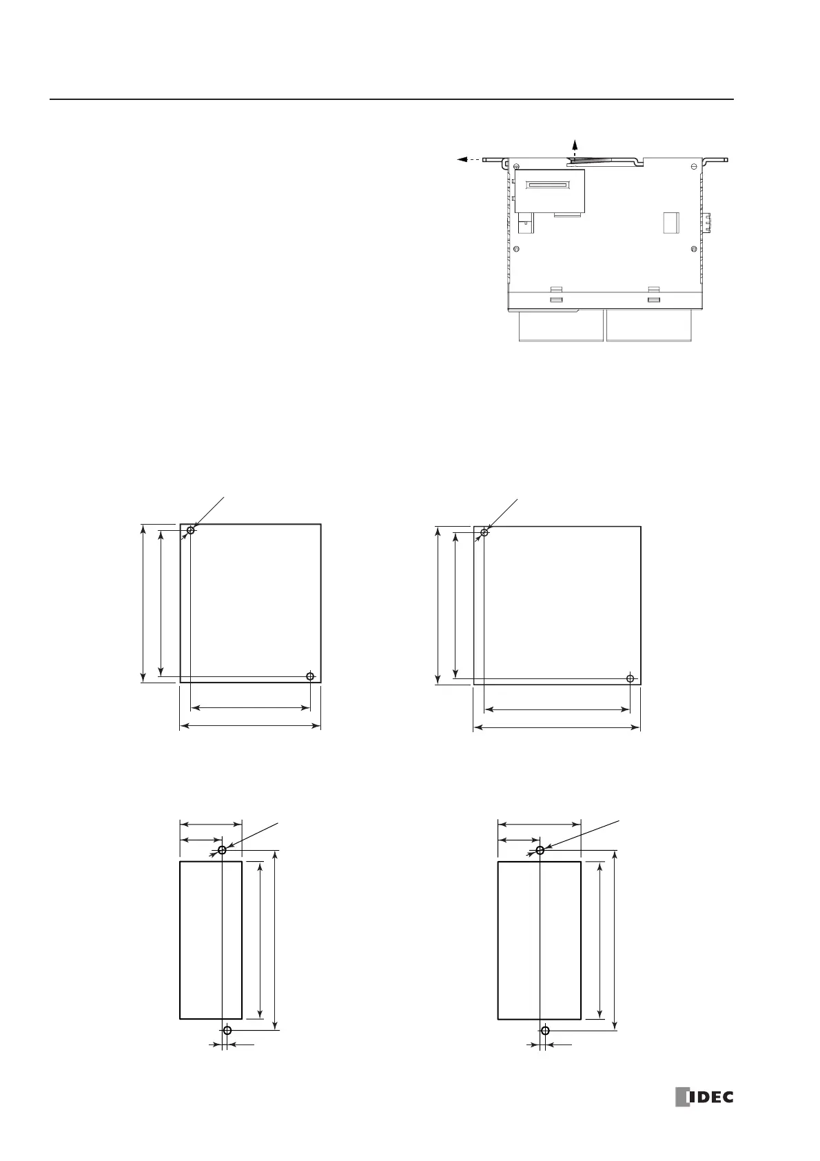
Removing the Direct Mounting Strip
1. Insert a flat screwdriver under the latch of the direct
mounting strip to release the latch (A).
2. Pull out the direct mounting strip (B).
Mounting Hole Layout for Direct Mounting on Panel Surface
Make mounting holes of ø4.3 mm as shown below and use M4 screws (6 or 8 mm long) to mount the MicroSmart modules
on the panel surface.
CPU Modules
FC4A-C10R2, FC4A-C10R2C, FC4A-C24R2, FC4A-C24R2C
FC4A-C16R2, FC4A-C16R2C
FC4A-D20K3, FC4A-D20S3 FC4A-D20RK1, FC4A-D20RS1,
FC4A-D40K3, FC4A-D40S3
(A)
(B)
83.0
95.0
2-ø4.3
83.0
90.0
83.0
90.0
68.0
80.0
2-ø4.3
All dimensions in mm.
103.0
90.0
2-ø4.3
24.1
35.4
3.0
103.0
90.0
2-ø4.3
24.1
47.5
3.0

Table of Contents

Questions and Answers:

Question and Answer IconNeed help?

Do you have a question about the IDEC FC4A-C16R2 and is the answer not in the manual?

IDEC FC4A-C16R2 Specifications

General IconGeneral
BrandIDEC
ModelFC4A-C16R2
CategoryController
LanguageEnglish

Related product manuals