17: USER COMMUNICATION INSTRUCTIONS
17-10 « FC4A MICROSMART USER’S MANUAL »
BCC (Block Check Character)
Block check characters can be appended to the transmit data. The start position for the BCC calculation can be selected
from the first byte through the 15th byte. The BCC, calculated in either XOR or ADD, can be 1 or 2 digits.
Upgraded CPU modules can also use ADD-2comp, Modbus ASCII, and Modbus RTU to calculate the BCC.
BCC Calculation Start Position
The start position for the BCC calculation can be specified from the first byte through the 15th byte. The BCC is calculated
for the range starting at the designated position up to the byte immediately before the BCC of the transmit data.
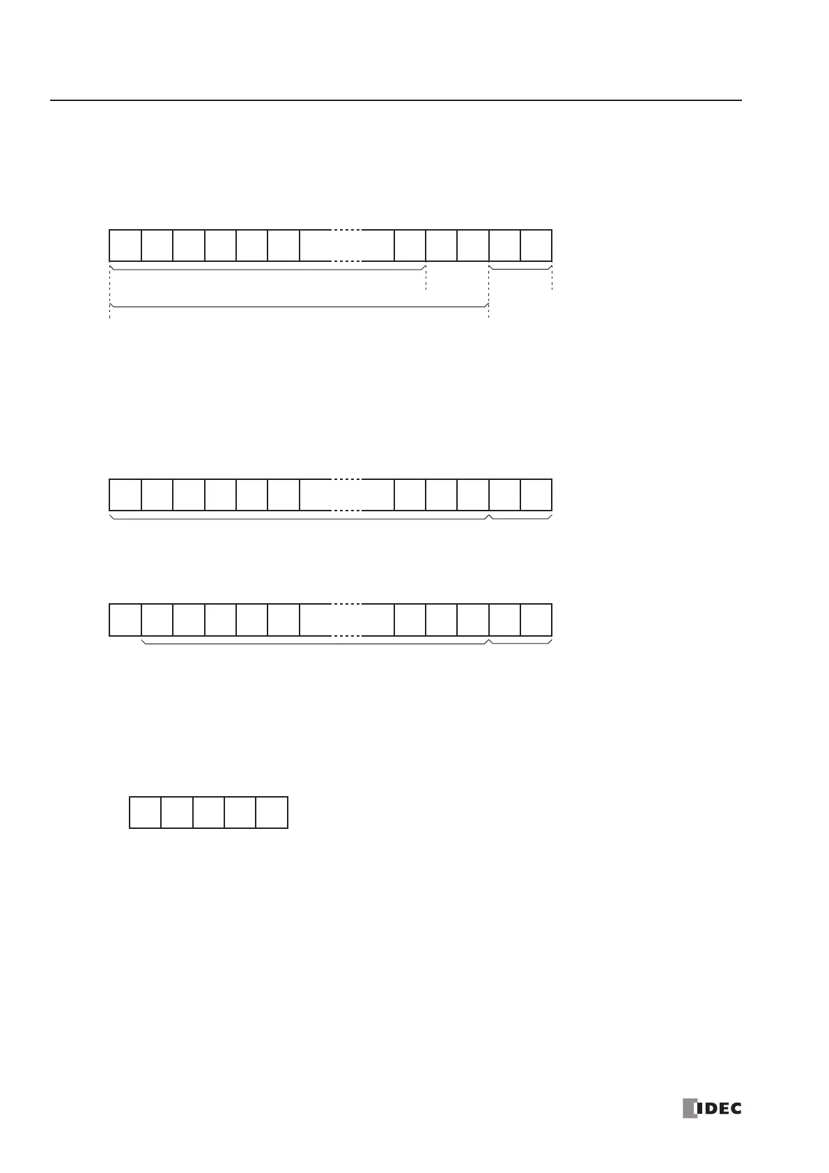
Example: Transmit data consists of 17 bytes plus 2 BCC digits.
(1) Calculation start position = 1
(2) Calculation start position = 2
BCC Calculation Formula
BCC calculation formula can be selected from XOR (exclusive OR) or ADD (addition) operation. ADD-2comp, Modbus
ASCII, and Modbus RTU can also be selected for the upgraded CPU modules, using WindLDR ver. 4.40 or higher.
Example: Conversion results of transmit data consist of 41h, 42h, 43h, 44h, and 45h.
(1) BCC calculation formula = XOR
Calculation result = 41h ⊕ 42h ⊕ 43h ⊕ 44h ⊕ 45h = 41h
(2) BCC calculation formula = ADD
Calculation result = 41h + 42h + 43h + 44h + 45h = 14Fh → 4Fh (Only the last 1 or 2 digits are used as BCC.)
(3) BCC calculation formula = ADD-2comp
Calculation result = B1
(4) BCC calculation formula = Modbus ASCII
Calculation result = A8
(5) BCC calculation formula = Modbus RTU
Calculation result = 91h 50h