17: USER COMMUNICATION INSTRUCTIONS
17-16 « FC4A MICROSMART USER’S MANUAL »
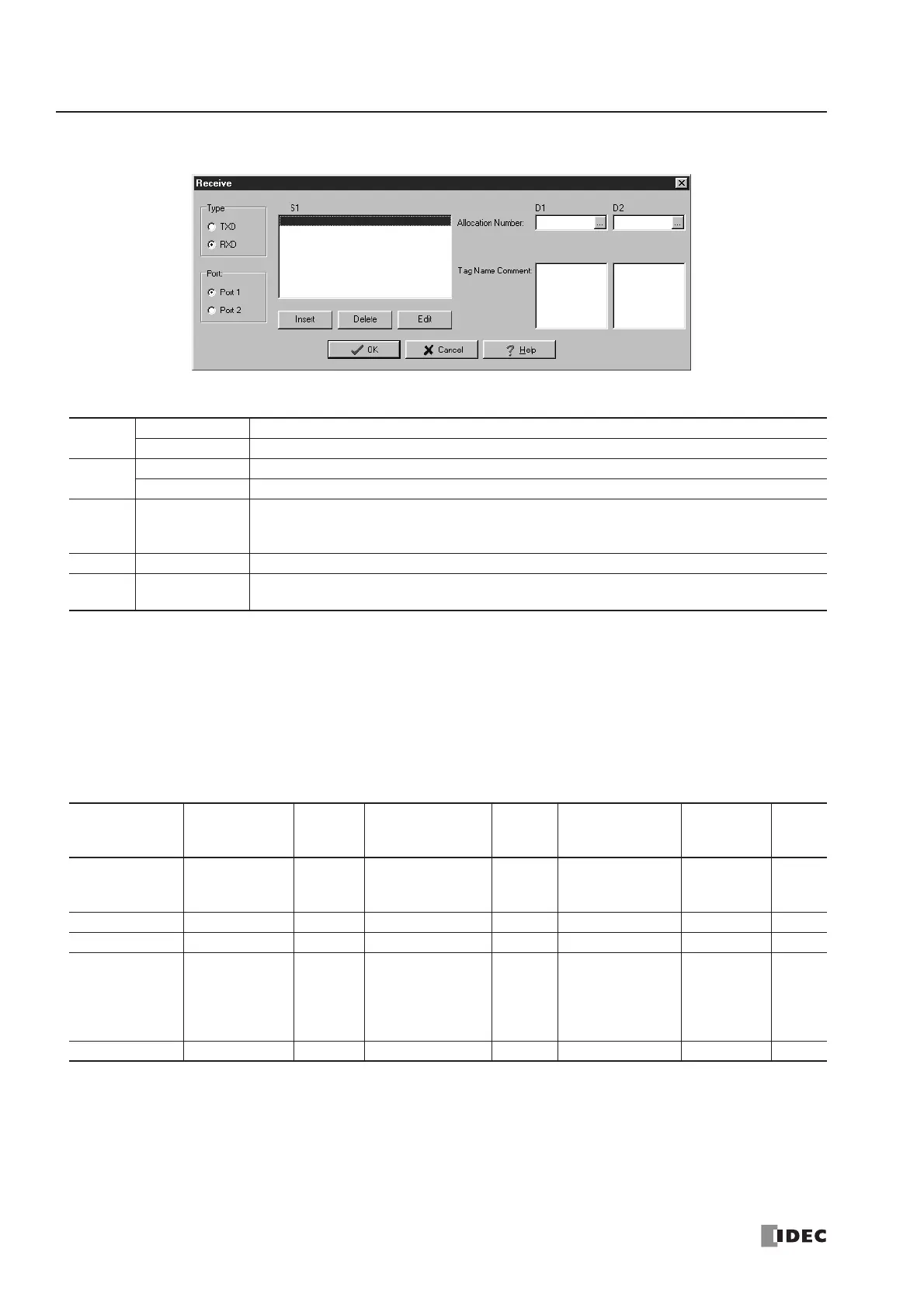
User Communication Receive Instruction Dialog Box in WindLDR
Selections and Operands in Receive Instruction Dialog Box
Receive Format
Receive format, designated by source operand S1, specifies data registers to store received data, data digits for storing
data, data conversion type, and repeat cycles. A start delimiter and an end delimiter can be included in the receive format to
discriminate valid incoming communication. When some characters in the received data are not needed, “skip” can be
used to ignore a specified number of characters. BCC code can also be appended to the receive format to verify the
received data. One RXD instruction can receive 200 bytes of data at the maximum.
S1 (Source 1)
Designating Data Register as S1
When a data register is designated as source operand S1, receive digits and conversion type must also be designated. The
received data is divided into a block of specified receive digits, converted in a specified conversion type, and stored to the
designated data register. Conversion types are available in ASCII to Binary, ASCII to BCD, and no conversion.
When repeat is designated, received data is divided, converted, and stored into data registers as many as the repeat cycles,
starting with the designated data register. Repeat cycles can be up to 99.
Type
TXD Transmit instruction
RXD Receive instruction
Port
Port 1 Receive user communication through port 1 (RXD1)
Port 2 Receive user communication through port 2 (RXD2)
S1 Source 1
Enter the receive format in this area.
The receive format can include a start delimiter, data register to store incoming data, end
delimiter, BCC, and skip.
D1 Destination 1 Receive completion output can be an output or internal relay.
D2 Destination 2
Receive status register can be data register D0 through D1298 or D2000 through D7998.
The next data register stores the byte count of received data.
Receive
Format
Operand
Receive
Digits
(Bytes)
Conversion Type Repeat BCC Calculation
Calculation
Start
Position
Skip
Bytes
Data Register
D0-D1299
D2000-D7999
1-4
1-5
1-2
A: ASCII to Binary
B: ASCII to BCD
–: No conversion
1-99 — — —
Start Delimiter 00h-7Fh (FFh) — No conversion — — — —
End Delimiter 00h-7Fh (FFh) — No conversion — — — —
BCC — 1-2
A: Binary to ASCII
–: No conversion
—
X: XOR
A: ADD
C: Add-2comp
M: Modbus ASCII
M: Modbus RTU
1-15 —
Skip ——————1-99