17: USER COMMUNICATION INSTRUCTIONS
« FC4A MICROSMART USER’S MANUAL » 17-21
BCC (Block Check Character)
The MicroSmart has an automatic BCC calculation function to detect a communication error in incoming data. If a BCC
code is designated in the receive format of a RXD instruction, the MicroSmart calculates a BCC value for a specified start-
ing position through the position immediately preceding the BCC and compares the calculation result with the BCC code
in the received incoming data. The start position for the BCC calculation can be specified from the first byte through the
15th byte. The BCC, calculated in either XOR or ADD, can be 1 or 2 digits.
Upgraded CPU modules can also use ADD-2comp, Modbus ASCII, and Modbus RTU to calculate the BCC.
When an end delimiter is not used in the RXD instruction, the BCC code must be positioned at the end of the receive for-
mat designated in Source 1 operand. When an end delimiter is used, the BCC code must be immediately before or after the
end delimiter. The MicroSmart reads a specified number of BCC digits in the incoming data according to the receive for-
mat to calculate and compare the received BCC code with the BCC calculation results.
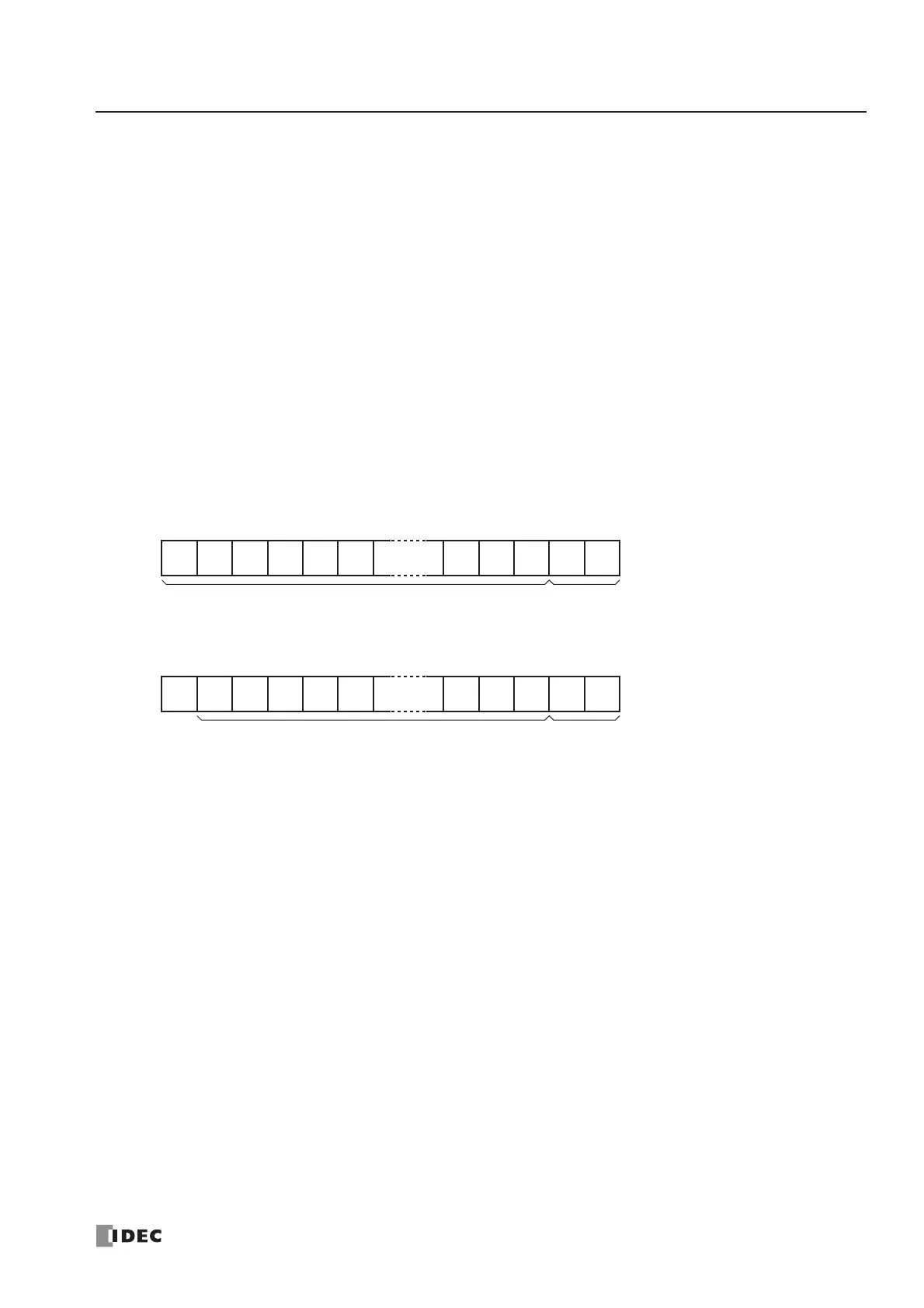
BCC Calculation Start Position
The start position for the BCC calculation can be specified from the first byte through the 15th byte. The BCC is calculated
for the range starting at the designated position up to the byte immediately before the BCC of the receive data.
Example: Received data consists of 17 bytes plus 2 BCC digits.
(1) Calculation start position = 1
(2) Calculation start position = 2
BCC Calculation Formula
BCC calculation formula can be selected from XOR (exclusive OR) or ADD (addition) operation. ADD-2comp, Modbus
ASCII, and Modbus RTU can also be selected for the upgraded CPU modules.
Example: Incoming data consists of 41h, 42h, 43h, 44h, and 45h.
(1) BCC Calculation formula = XOR
Calculation result = 41h ⊕ 42h ⊕ 43h ⊕ 44h ⊕ 45h = 41h
(2) BCC Calculation formula = ADD
Calculation result = 41h + 42h + 43h + 44h + 45h = 14Fh → 4Fh (Only the last 1 or 2 digits are used as BCC.)
(3) BCC calculation formula = ADD-2comp
Calculation result = B1
(4) BCC calculation formula = Modbus ASCII
Calculation result = A8
(5) BCC calculation formula = Modbus RTU
Calculation result = 91h 50h