20: PULSE INSTRUCTIONS
« FC4A MICROSMART USER’S MANUAL » 20-5
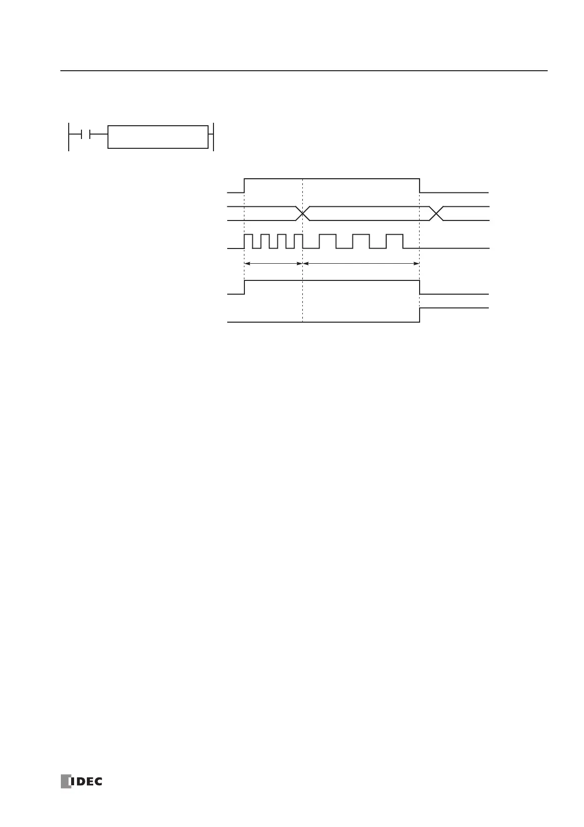
Timing Chart for Disable Pulse Counting
This program demonstrates a timing chart of the PULS2 instruction without pulse counting.
D1
M20
I1
PULS
2
S1
D100
D102 = 0 (disable pulse counting)
Output Pulse Q1
Output Pulse Frequency D101
FR1
FR1
Start Input I1
• When input I1 is turned on, PULS2 starts to generate output pulses at the frequency designated by the value
stored in data register D101. While the output pulses are sent out from output Q1, internal relay M20 remains on.
• When input I1 is turned off, PULS2 stops generating output pulses immediately, then internal relay M20 turns off
and internal relay M21 turns on.
• If the output pulse frequency value in D101 is changed while generating output pulses, the change takes effect in
the next scan. When changing the pulse frequency, make sure that the timing of the change is much slower than
the output pulse frequency, so that the pulse frequency is changed successfully.