20: P
ULSE
I
NSTRUCTIONS
20-12 « FC4A M
ICRO
S
MART
U
SER
’
S
M
ANUAL
»
Sample Program: PWM1
This program demonstrates a user program of the PWM1 instruction to generate pulses from output Q0, with an ON/OFF
ratio of 30% while input I0 is off or 60% when input I0 is on.
Operand Settings
Operand Function Description Allocation No. (Value)
S1+0 Output pulse frequency 217.86 Hz D0 (2)
S1+1 Pulse width ratio 30% or 60% D1 (30 or 60)
S1+2 Pulse counting Disable pulse counting D2 (0)
S1+3 Preset value (high word)
Not used
D3
S1+4 Preset value (low word) D4
S1+5 Current value (high word)
Not used
D5
S1+6 Current value (low word) D6
S1+7 Error status D7
D1+0 Pulse output ON
0: Pulse output OFF
1: Pulse output ON
M100
D1+1 Pulse output complete
0: Pulse output not complete
1: Pulse output complete
M101
D1+2 Pulse output overflow
0: Overflow not occurred
1: Overflow occurred (PWM1 only)
M102
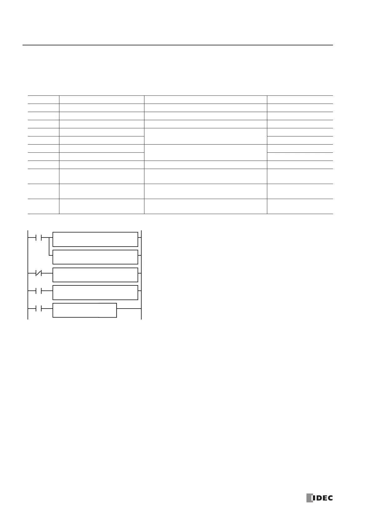
M8120
I0
M8120 is the initialize pulse special internal relay.
When the CPU starts, MOV(W) instructions store parameters to data regis-
ters D0 and D2.
D0 (output pulse frequency): 2 (217.86 Hz)
D2 (pulse counting): 0 (disable pulse counting)
When input I0 is off, D1 (pulse width ratio) stores 30 (30%).
When input I0 is on, D1 (pulse width ratio) stores 60 (60%).
When input I1 is on, PWM1 generates output pulses of a 30% or 60%
pulse width ratio from output Q0 depending whether input I0 is off or on,
respectively.
REPS1 –
2
MOV(W) D1 –
D0
REPS1 –
0
MOV(W)
D1 –
D2
REPS1 –
30
MOV(W) D1 –
D1
REPS1 –
60
MOV(W) D1 –
D1
I0
D1
M100
PWM
1
S1
D0
I1