2: MODULE SPECIFICATIONS
« FC4A MICROSMART USER’S MANUAL » 2-19
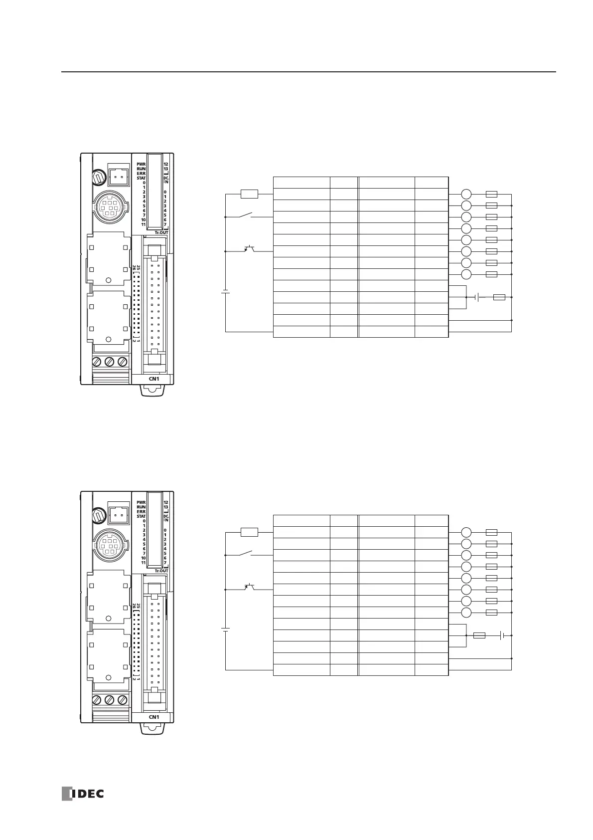
CPU Module Terminal Arrangement and I/O Wiring Diagrams (Slim Type)
FC4A-D20K3 (20-I/O Transistor Sink Output Type CPU Module)
Applicable Connector: FC4A-PMC26P (not supplied with the CPU module)
FC4A-D20S3 (20-I/O Transistor Source Output Type CPU Module)
Applicable Connector: FC4A-PMC26P (not supplied with the CPU module)
Terminal No. Input Terminal No. Output
26 I0 25 Q0
24 I1 23 Q1
22 I2 21 Q2
20 I3 19 Q3
18 I4 17 Q4
16 I5 15 Q5
14 I6 13 Q6
12 I7 11 Q7
10 I10 9 COM(–)
8 I11 7 COM(–)
6 I12 5 COM(–)
4 I13 3 +V
2 COM 1 +V
Source Input Wiring
• COM(–) terminals are connected together internally.
• COM and COM(–) terminals are not connected together internally.
• +V terminals are connected together internally.
• Connect a fuse appropriate for the load.
• For wiring precautions, see pages 3-13 through 3-17.
+
–
+
–
2-wire Sensor
24V DC
NPN
Sink Output Wiring
L
Fuse
L
L
+–
L
L
L
L
Load
L
Fuse
Terminal No. Input Terminal No. Output
26 I0 25 Q0
24 I1 23 Q1
22 I2 21 Q2
20 I3 19 Q3
18 I4 17 Q4
16 I5 15 Q5
14 I6 13 Q6
12 I7 11 Q7
10 I10 9 COM(+)
8 I11 7 COM(+)
6 I12 5 COM(+)
4 I13 3 –V
2 COM 1 –V
Sink Input Wiring
+
–
+
–
2-wire Sensor
24V DC
PNP
Source Output Wiring
L
Fuse
L
L
+–
L
L
L
L
Load
L
Fuse
• COM(+) terminals are connected together internally.
• COM and COM(+) terminals are not connected together internally.
• –V terminals are connected together internally.
• Connect a fuse appropriate for the load.
• For wiring precautions, see pages 3-13 through 3-17.