24: ANALOG I/O CONTROL
24-4 « FC4A MICROSMART USER’S MANUAL »
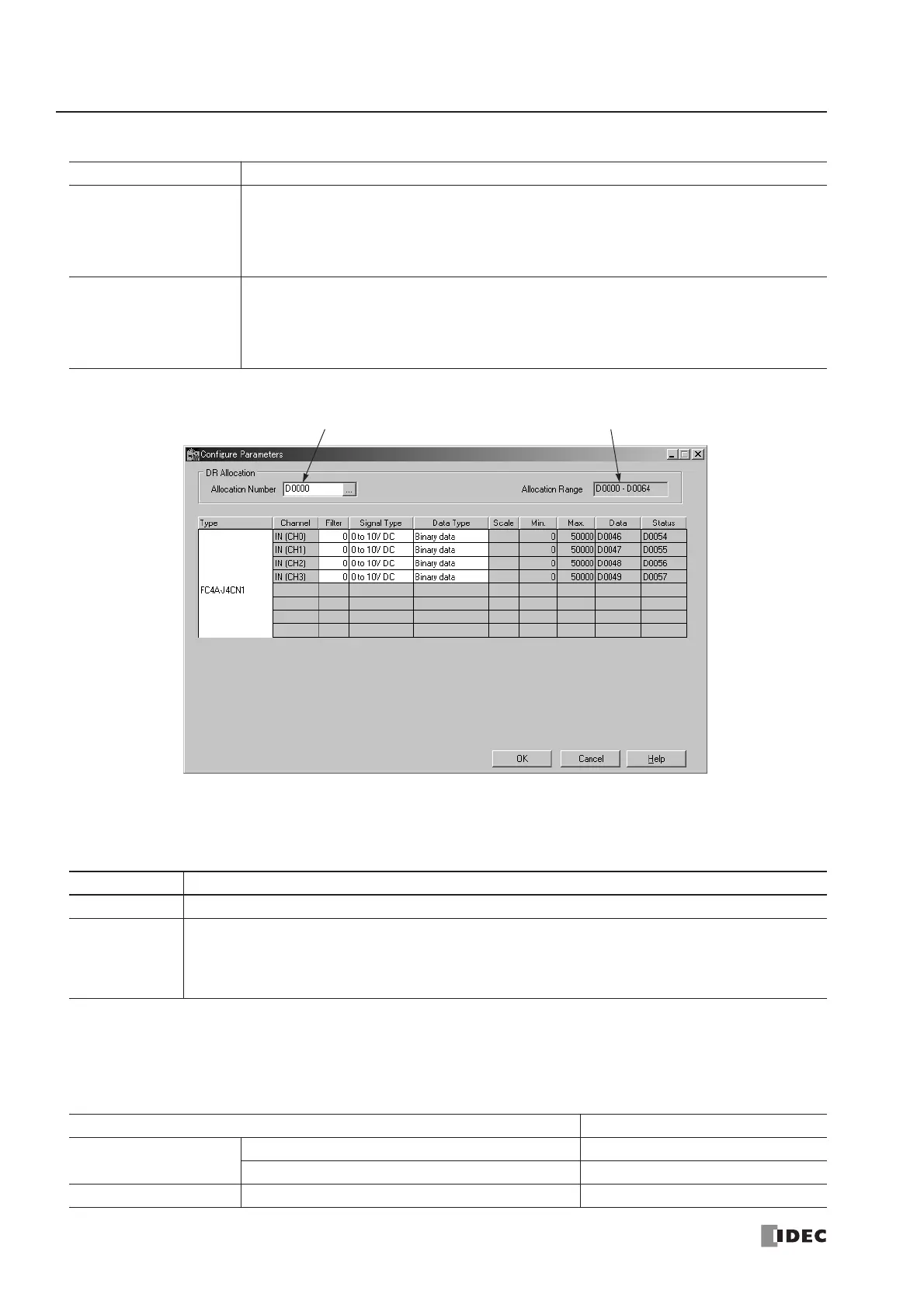
5. Select a DR allocation number (Ladder refresh type only).
6. Enter a filter value (Ladder refresh type analog input modules only).
The filter function is available for the FC4A-J4CN1, FC4A-J8C1, and FC4A-J8AT1 only. Filtering ensures smooth input
of analog data into the CPU module.
7. Select a signal type for each channel.
Click on the right of the Signal Type field, then a pull-down list appears to show all available input or output signal types.
When you do not use any input or output signal, select the default value or Not used for the channel.
CPU Module DR Allocation
END Refresh Type
FC4A-L03A1
FC4A-L03AP1
FC4A-J2A1
FC4A-K1A1
DR allocation starts with D760 as default, and the first DR number cannot be changed.
One analog I/O module occupies 20 data registers. When a maximum of seven analog I/O
modules are used, data registers D760 through D899 are used for analog I/O control.
Ladder Refresh Type
FC4A-J4CN1
FC4A-J8C1
FC4A-J8AT1
FC4A-K2C1
The first data register can be selected as required. Enter the first DR number used for analog
I/O control.
One analog input module occupies a maximum of 65 data registers.
One analog output module occupies 15 data registers.
Filter Value Description
0Without filter function
1 to 255
The average of N pieces of analog input data is read as analog input data, where N is the designated
filter value.
Analog I/O Module For unused channel, select
END Refresh Type
FC4A-L03A1, FC4A-J2A1 0 to 10V DC
FC4A-L03AP1 Type K
Ladder Refresh Type FC4A-J4CN1, FC4A-J8C1, FC4A-J8AT1, FC4A-K2C1 Not used
--------------------------------------------------------------------------------------------------------------------------------------------------------------------------------------------=