28: AS-INTERFACE MASTER COMMUNICATION
28-22 « FC4A MICROSMART USER’S MANUAL »
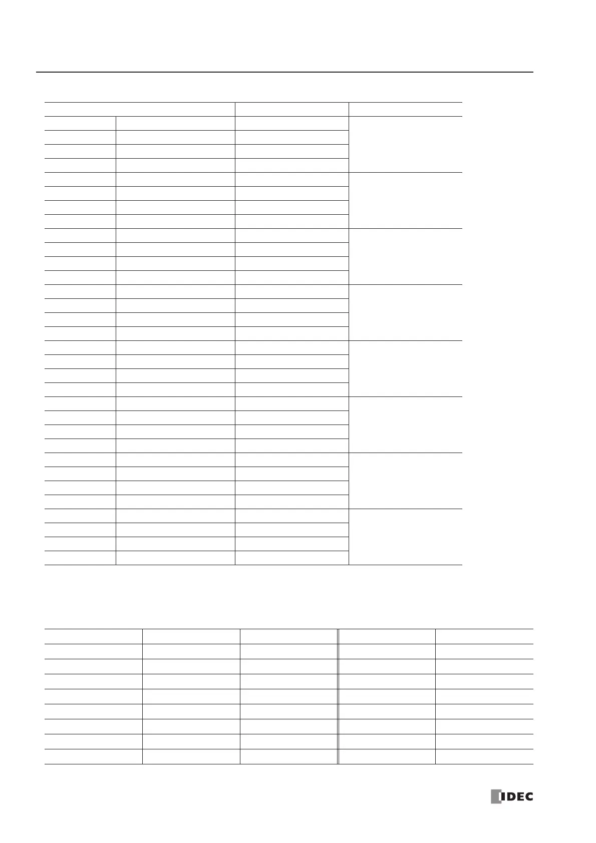
• Analog Output Data
For example, when analog input slaves 1, 13 and 20, analog output slaves 5 and 25, and analog I/O slaves 14 and 21 are
used, the analog I/O slave data will be allocated by configuration as shown below and maintained until the next configura-
tion is executed. Four channels (8 bytes) are always reserved for each slave.
Analog Output Channel No. Data Format
D1732 Bytes 0 and 1 Channel 1
1st data
(AO0)
D1733 Bytes 2 and 3 Channel 2
D1734 Bytes 4 and 5 Channel 3
D1735 Bytes 6 and 7 Channel 4
D1736 Bytes 8 and 9 Channel 1
2nd data
(AO1)
D1737 Bytes 10 and 11 Channel 2
D1738 Bytes 12 and 13 Channel 3
D1739 Bytes 14 and 15 Channel 4
D1740 Bytes 16 and 17 Channel 1
3rd data
(AO2)
D1741 Bytes 18 and 19 Channel 2
D1742 Bytes 20 and 21 Channel 3
D1743 Bytes 22 and 23 Channel 4
D1744 Bytes 24 and 25 Channel 1
4th data
(AO3)
D1745 Bytes 26 and 27 Channel 2
D1746 Bytes 28 and 29 Channel 3
D1747 Bytes 30 and 31 Channel 4
D1748 Bytes 32 and 33 Channel 1
5th data
(AO4)
D1749 Bytes 34 and 35 Channel 2
D1750 Bytes 36 and 37 Channel 3
D1751 Bytes 38 and 39 Channel 4
D1752 Bytes 40 and 41 Channel 1
6th data
(AO5)
D1753 Bytes 42 and 43 Channel 2
D1754 Bytes 44 and 45 Channel 3
D1755 Bytes 46 and 47 Channel 4
D1756 Bytes 48 and 49 Channel 1
7th data
(AO6)
D1757 Bytes 50 and 51 Channel 2
D1758 Bytes 52 and 53 Channel 3
D1759 Bytes 54 and 55 Channel 4
D1760 Bytes 56 and 57 —
(reserved)
D1761 Bytes 58 and 59 —
D1762 Bytes 60 and 61 —
D1763 Bytes 62 and 63 —
Analog Slave Module Data Storage Analog Input Slave Data Storage Analog Output Slave
1st D1700-D1703 Slave 1 D1732-D1735 Unused
2nd D1704-D1707 Unused D1736-D1739 Slave 5
3rd D1708-D1711 Slave 13 D1740-D1743 Unused
4th D1712-D1715 Slave 14 D1744-D1747 Slave 14
5th D1716-D1719 Slave 20 D1748-D1751 Unused
6th D1720-D1723 Slave 21 D1752-D1755 Slave 21
7th D1724-D1727 Unused D1756-D1759 Slave 25
(8th) (D1728-D1731) (reserved) (D1760-D1763) (reserved)