2: MODULE SPECIFICATIONS
2-32 « FC4A MICROSMART USER’S MANUAL »
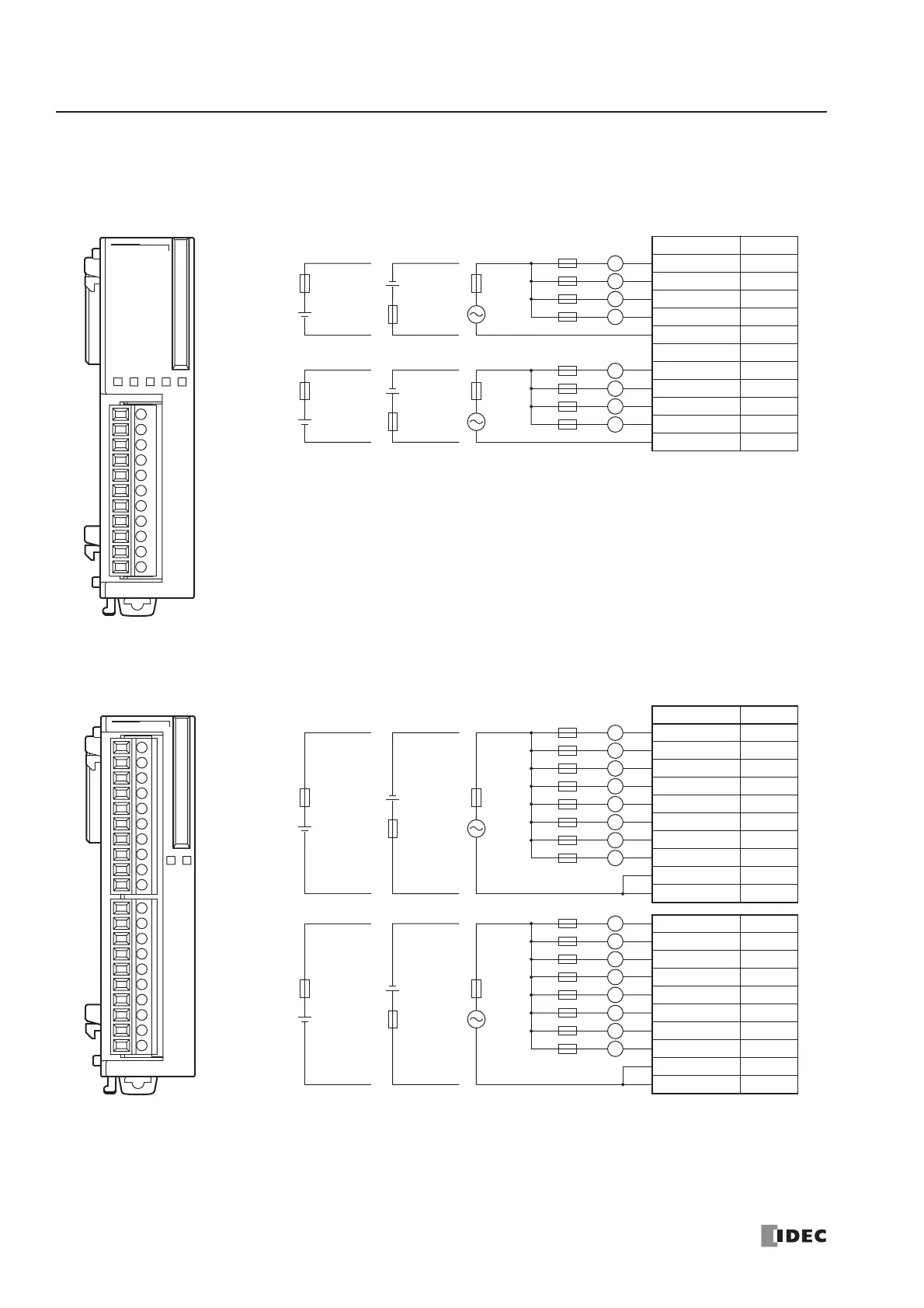
Relay Output Module Terminal Arrangement and Wiring Diagrams
FC4A-R081 (8-point Relay Output Module) — Screw Terminal Type
Applicable Terminal Block: FC4A-PMT11P (supplied with the output module)
FC4A-R161 (16-point Relay Output Module) — Screw Terminal Type
Applicable Terminal Block: FC4A-PMT10P (supplied with the output module)
L
7 COM1
0
1
2
3
4
5
6
7
Ry.OUT
1023
COM0
NC 456
Terminal No. Output
0Q0
1Q1
2Q2
3Q3
COM0 COM0
NC NC
4Q4
5Q5
6Q6
7Q7
COM1 COM1
L
Fuse
L
L
L
AC
Fuse
Fuse
DC
DC
Load
L
L
L
Fuse
+
–
AC
Fuse
Fuse
DC
DC
+
–
+
–
+
–
• COM0 and COM1 terminals are not connected together internally.
• Connect a fuse appropriate for the load.
• For output wiring precautions, see page 3-14.
Fuse
0
1
2
3
4
5
6
7
10
11
12
13
14
15
16
17
Ry.OUT
COM1 COM1
10 11 12 13 14 15 16 17
0 1 2 3 4 5 6 7
COM0 COM0
L
Terminal No. Output
0Q0
1Q1
2Q2
3Q3
4Q4
5Q5
6Q6
7Q7
COM0 COM0
COM0 COM0
10 Q10
11 Q11
12 Q12
13 Q13
14 Q14
15 Q15
16 Q16
17 Q17
COM1 COM1
COM1 COM1
L
Fuse
+
–
L
L
L
AC
Fuse
Fuse
DC
DC
+
–
Load
L
L
L
L
L
Fuse
+
–
L
L
L
AC
Fuse
Fuse
DC
DC
+
–
L
L
L
• COM0 terminals are connected together internally.
• COM1 terminals are connected together internally.
• COM0 and COM1 terminals are not connected together internally.
• Connect a fuse appropriate for the load.
• For output wiring precautions, see page 3-14.
Fuse