2: MODULE SPECIFICATIONS
2-34 « FC4A MICROSMART USER’S MANUAL »
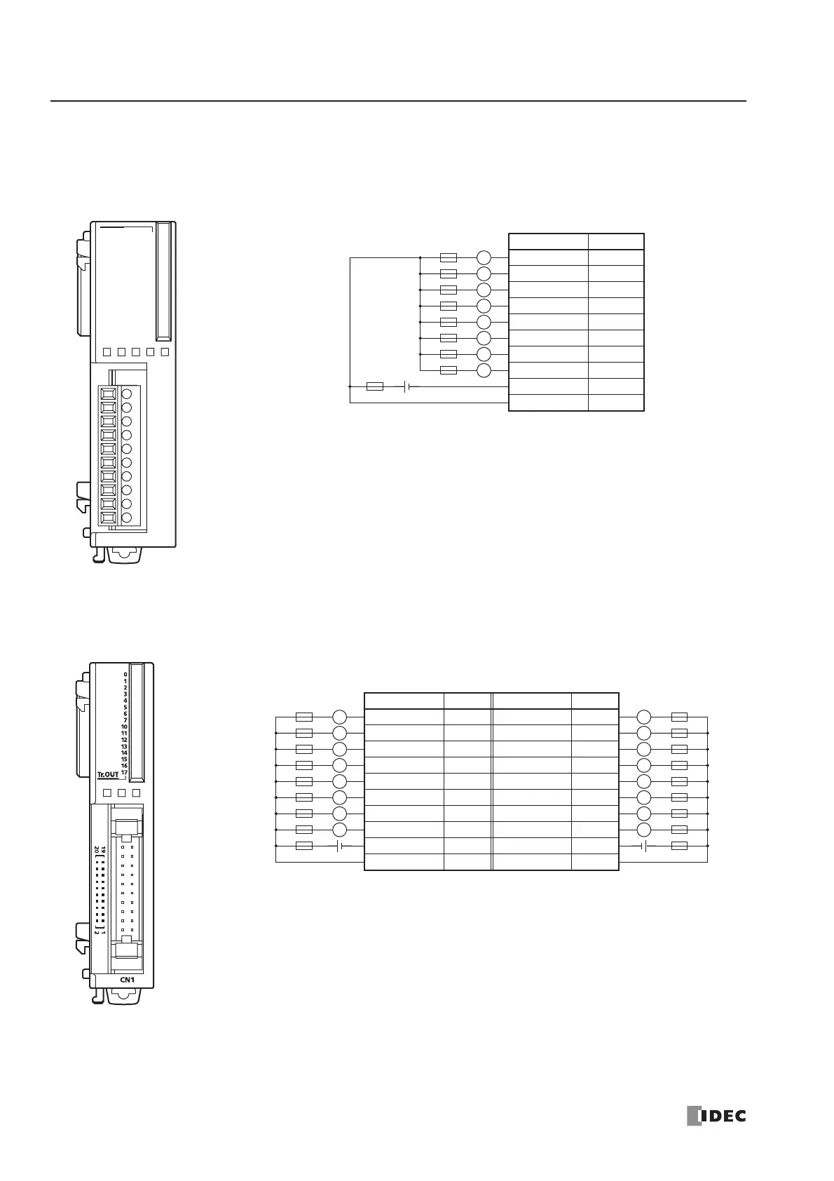
Transistor Sink Output Module Terminal Arrangement and Wiring Diagrams
FC4A-T08K1 (8-point Transistor Sink Output Module) — Screw Terminal Type
Applicable Terminal Block: FC4A-PMT10P (supplied with the output module)
FC4A-T16K3 (16-point Transistor Sink Output Module) — Connector Type
Applicable Connector: FC4A-PMC20P (not supplied with the output module)
L
Terminal No. Output
0Q0
1Q1
2Q2
3Q3
4Q4
5Q5
6Q6
7Q7
COM(–) COM(–)
+V +V
Fuse
L
L
+–
L
L
L
L
Load
L
COM(–)
+V
0
1
2
3
4
5
6
7
Tr.OUT
01234567
• Connect a fuse appropriate for the load.
• For output wiring precautions, see page 3-14.
Fuse
• COM(–) terminals are connected together internally.
• +V terminals are connected together internally.
• Connect a fuse appropriate for the load.
• For output wiring precautions, see page 3-14.
Terminal No. Output Terminal No. Output
20 Q0 19 Q10
18 Q1 17 Q11
16 Q2 15 Q12
14 Q3 13 Q13
12 Q4 11 Q14
10 Q5 9 Q15
8Q67Q16
6Q75Q17
4 COM(–) 3 COM(–)
2+V1+V
L
L
L
+–
L
L
L
L
Load
L
Fuse
L
L
L
+–
L
L
L
L
Load
L
Fuse