2: MODULE SPECIFICATIONS
« FC4A MICROSMART USER’S MANUAL » 2-51
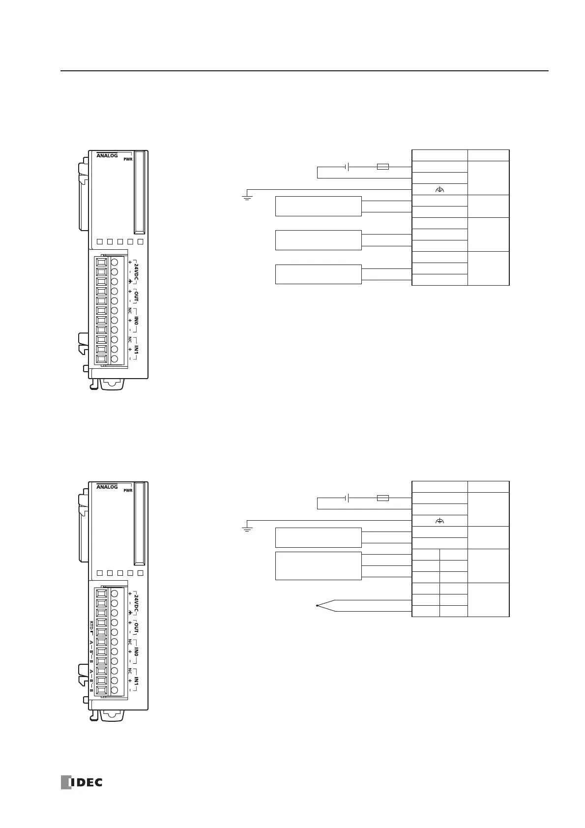
Analog I/O Module Terminal Arrangement and Wiring Diagrams
FC4A-L03A1 (Analog I/O Module) — Screw Terminal Type
Applicable Terminal Block: FC4A-PMT11P (supplied with the analog I/O module)
FC4A-L03AP1 (Analog I/O Module) — Screw Terminal Type
Applicable Terminal Block: FC4A-PMT11P (supplied with the analog I/O module)
Terminal No. Channel
+
24V DC–
+
OUT
–
NC
IN0+
–
NC
IN1+
–
• Connect a fuse appropriate for the applied voltage and current draw, at the position shown in the
diagram. This is required when equipment containing the MicroSmart is destined for Europe.
• Do not connect any wiring to unused terminals.
• Before turn on the power, make sure that wiring to the analog I/O module is correct. If wiring is
incorrect, the analog I/O module may be damaged.
Fuse
+–
24V DC
Analog voltage/current
input device
+
–
+
–
+
–
Analog voltage/current
output device
Analog voltage/current
output device
Terminal No. Channel
+
24V DC–
+
OUT
–
NC A
IN0+B’
–B
NC A
IN1+B’
–B
Thermocouple
• Connect a fuse appropriate for the applied voltage and current draw, at the position shown in the
diagram. This is required when equipment containing the MicroSmart is destined for Europe.
• When connecting a resistance thermometer, connect the three wires to RTD (resistance temper-
ature detector) terminals A, B’, and B of input channel IN0 or IN1.
• When connecting a thermocouple, connect the two wires to terminals + and – of input channels
IN0 or IN1.
• Do not connect any wiring to unused terminals.
• Do not connect the thermocouple to a hazardous voltage (60V DC or 42.4V peak or higher).
Fuse
+–
24V DC
Resistance
thermometer
+
–
B
+
–
A
B’
Analog voltage/current
input device