2: MODULE SPECIFICATIONS
2-52 « FC4A MICROSMART USER’S MANUAL »
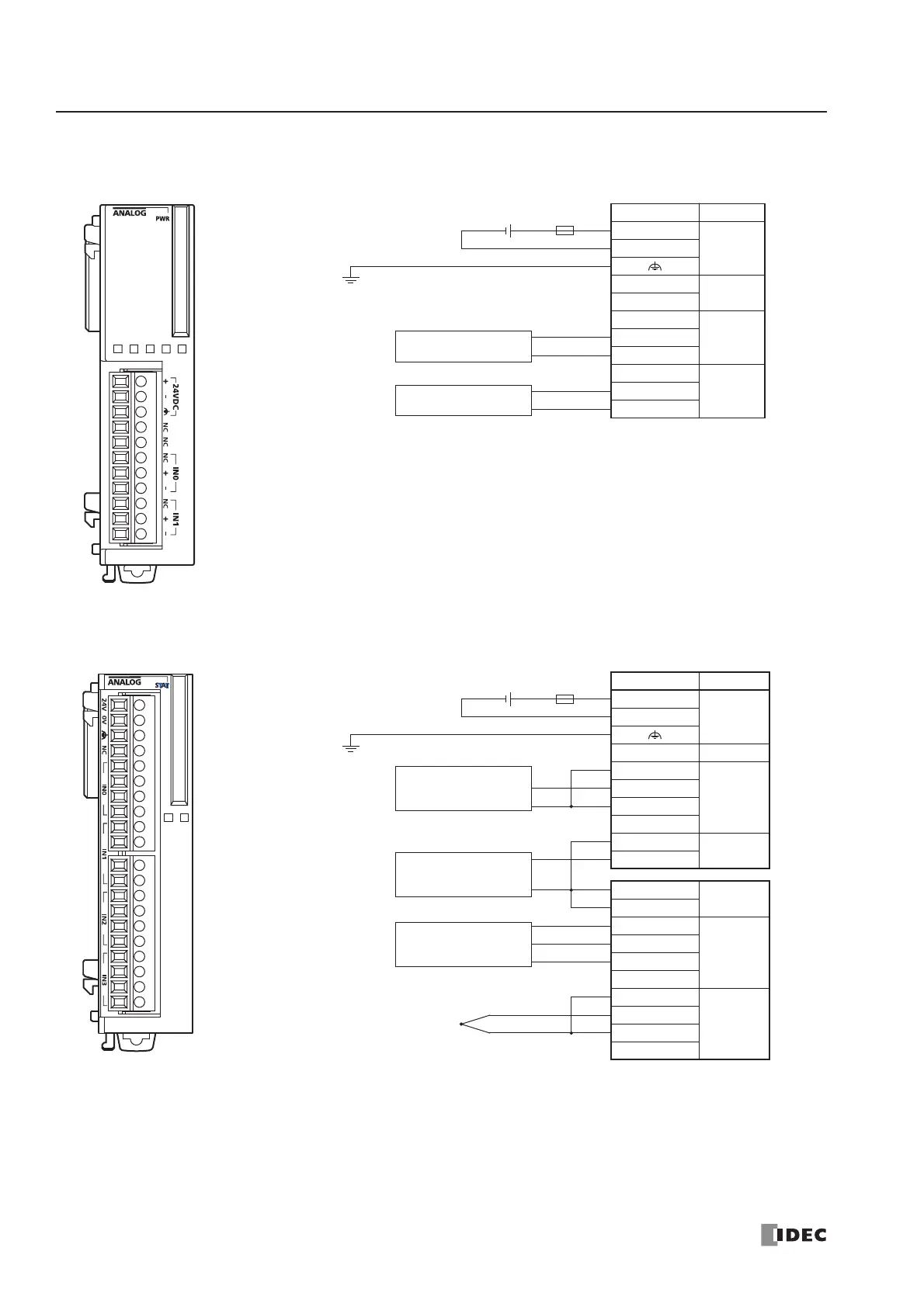
FC4A-J2A1 (Analog Input Module) — Screw Terminal Type
Applicable Terminal Block: FC4A-PMT11P (supplied with the analog input module)
FC4A-J4CN1 (Analog Input Module) — Screw Terminal Type
Applicable Terminal Block: FC4A-PMT10P (supplied with the analog input module)
Terminal No. Channel
+
24V DC–
NC
—
NC
NC
IN0+
–
NC
IN1+
–
• Connect a fuse appropriate for the applied voltage and current draw, at the position shown in the
diagram. This is required when equipment containing the MicroSmart is destined for Europe.
• Do not connect any wiring to unused terminals.
Fuse
+–
24V DC
+
–
+
–
Analog voltage/current
output device
Analog voltage/current
output device
Terminal No. Channel
24V
24V DC0V
NC —
CS
IN0
+
–
I–
CS
IN1
+
–
IN1
I–
CS
IN2
+
–
I–
CS
IN3
+
–
I–
• Connect a fuse appropriate for the applied voltage and current draw, at the position shown in the diagram. This is
required when equipment containing the MicroSmart is destined for Europe.
• When connecting a resistance thermometer, connect three wires B, B’, and A to the CS (current sense), +, and – termi-
nals of input channels IN0 through IN3, respectively.
• When connecting a thermocouple, connect the + wire to the + terminal and the – wire to the CS and – terminals.
• Do not connect the thermocouple to a hazardous voltage (60V DC or 42.4V peak or higher).
• Do not connect any wiring to unused terminals.
• – terminals of input channels IN0 through IN3 are interconnected.
Fuse
+–
24V DC
Analog voltage
output device
–
+
Resistance
thermometer
A
B
B’
Thermocouple
+
–
NC
–
+
NC
NC
Analog current
output device