32 / 34
All information contained in this document is property of IDS. All rights reserved
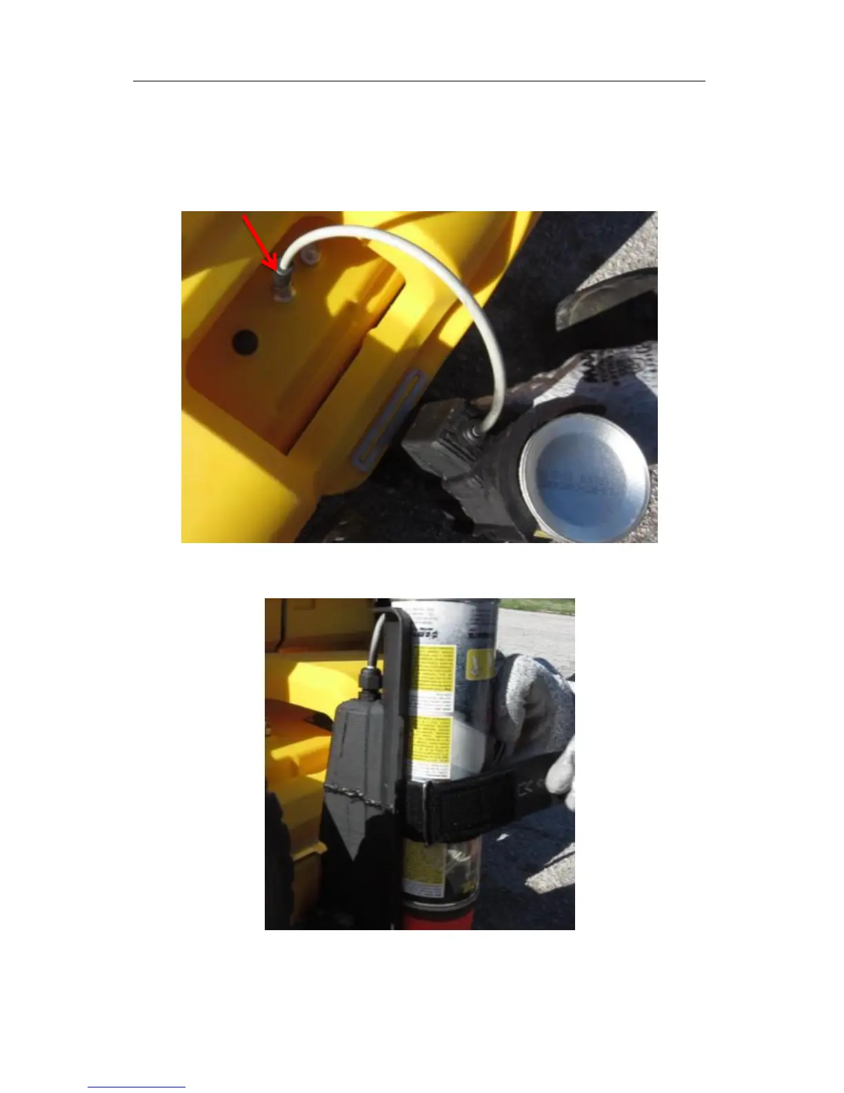
3. Close the locking system in the lower part of the spray support;
4. Connect the Spray cable to the dedicated connector (Fig. 4.12);
5. Insert the spray can into the support with the dispenser facing downward (Error!
eference source not found.).
Fig. 4.12 – Spray support cable connection
Fig. 4.13 – Spray can insertion