About Advanced Features & Operation
OUTSIDE SENSOR - To view an Outside Sensor
(step #10, page 13), press and hold the FAN button
for two seconds until the Outside icon appears. If
an optional outside sensor is connected, the outside
temperature will appear on the display. To exit the
outside temperature display, press any button.
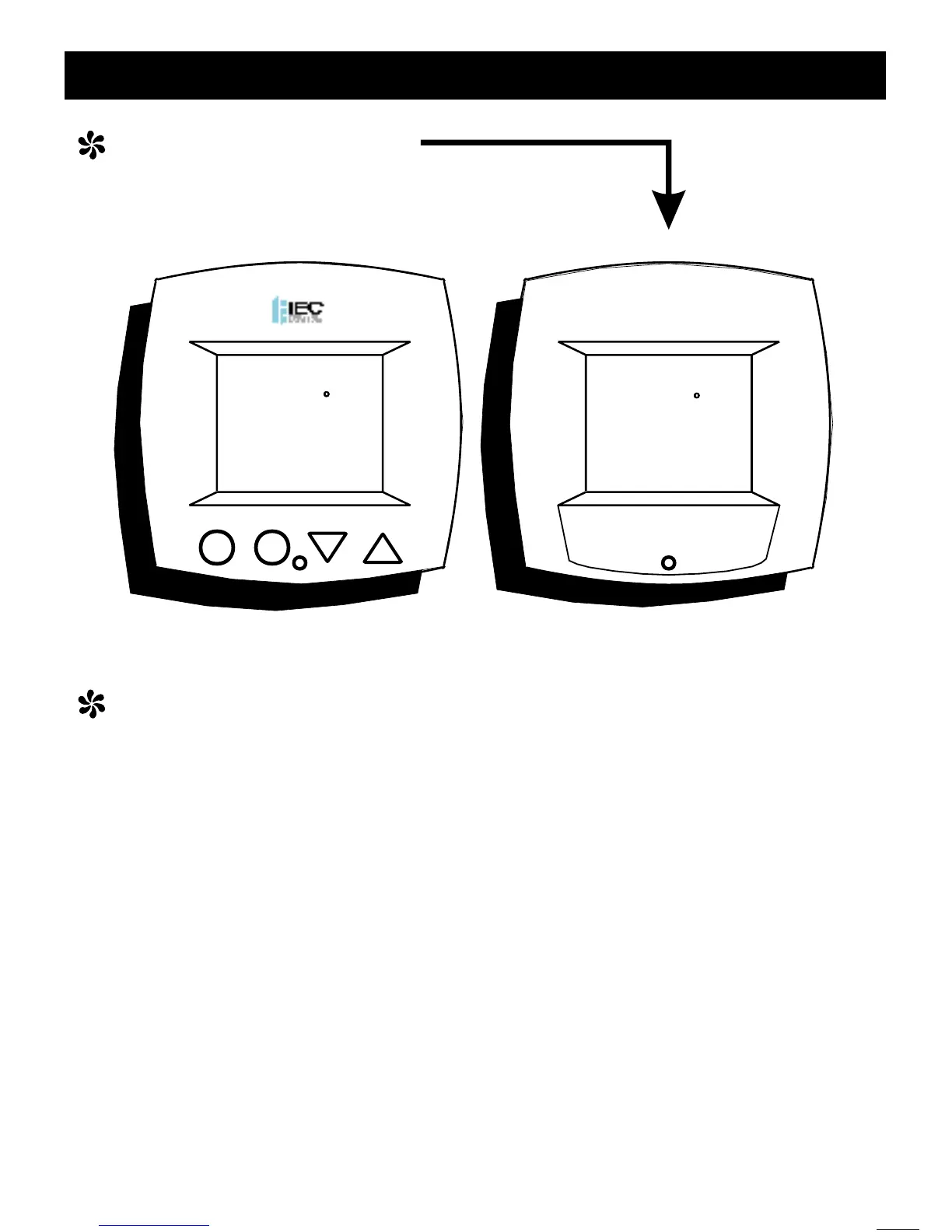
LOCKING COVER
w/Tamper Proof Screws
(G100-71520308 w/ logo
G100-71520309 w/out logo)
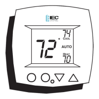
72
72
74
74
70
70
COOL
COOL
HEAT
HEAT
AUTO
AUTO
Page 22
About Advanced Features & Operation
REMOTE SENSOR (P/N G100-71520307) - The
thermostat is programmed from the factory to auto-
OVER
RIDE
Page 23
matically recognize when a Remote
Sensor is connected (step #10, page
13).
The Remote Sensor measures indoor
air temperature and sends this infor-
mation to the thermostat; it measures
temperature with a range of 32 to
99 F.
The Remote Sensor should be con-
nected to the thermostat using solid
conductor CAT 5, CAT 5e, or CAT 6 type network
communication cable. This is an unshielded cable with
four twisted pairs of 24 gauge solid wire; DO NOT use
stranded cable. The cable length should not exceed
250 feet. If less than 75 feet of cable is required to
connect the thermostat to the Remote Sensor, a three
conductor thermostat cable (18-24 gauge) may be
used; this cable is NOT suitable for any length greater
than 75 feet.
IMPORTANT: Do no use shielded wire. Do not run
sensor wiring in the same conduit as the 24VAC therm-
ostat wiring. Electrical interference may cause the
sensor to give incorrect temperature readings.
Note: If a remote sensor is connected to this ther-
mostat, then the fan should be programmed for
continuous operation (step #5, page 11). This will
provide airflow over the remote sensor and provide
more accurate temperature readings.
See the Remote Sensor instructions for further details.
 Loading...