9
UK
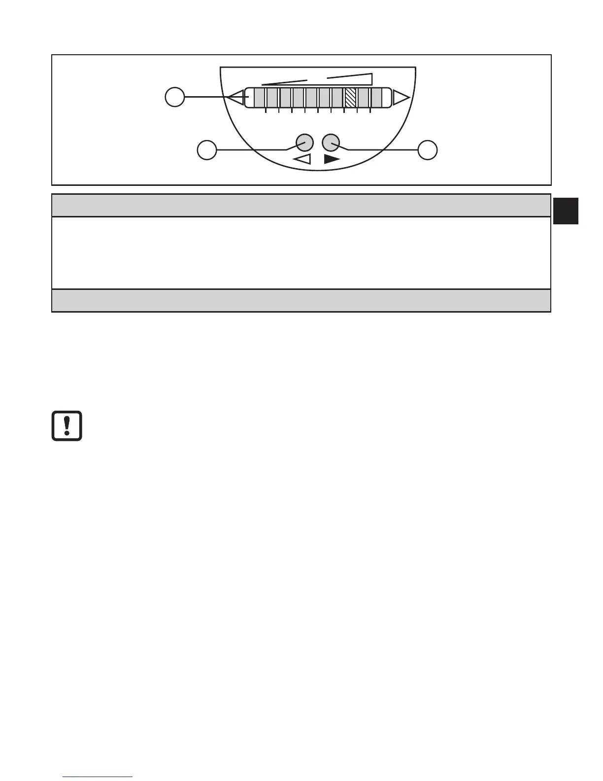
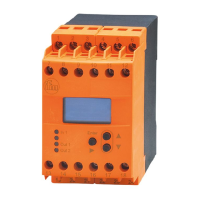
6 Operating and display elements
1: Operation indication
•The green LEDs indicate the current flow (LEDs 0 to 9 represent the range between flow
standstill and maximum flow)�
•A lit LED indicates the position of the switch point flow (SP1) (orange = output closed,
red = output open)�
2, 3: Setting buttons for adjustment and configuration
7 Parameter setting
Parameters can be set before installation and set-up of the unit or during opera-
tion�
If you change parameters during operation, this will influence the function�
► Ensure that there will be no malfunctions in your plant�
7.1 IO-Link
7.1.1 General information
This unit has an IO-Link communication interface which requires an IO-Link-capa-
ble module (IO-Link master) for operation�
The IO-Link interface enables direct access to the process and diagnostic data
and provides the possibility to set the parameters of the unit during operation�
In addition communication is possible via a point-to-point connection with a USB
adapter cable�
You will find more detailed information about IO-Link at www�ifm�com/gb/io-link�