10
7.1.2 Device-specific information
You will find the IODDs necessary for the configuration of the IO-Link unit and
detailed information about process data structure, diagnostic information and
parameter addresses at www�ifm�com/gb/io-link�
7.1.3 Parameter setting tools
You will find all necessary information about the required IO-Link hardware and
software at www�ifm�com/gb/io-link�
7.1.4 Adjustable parameters
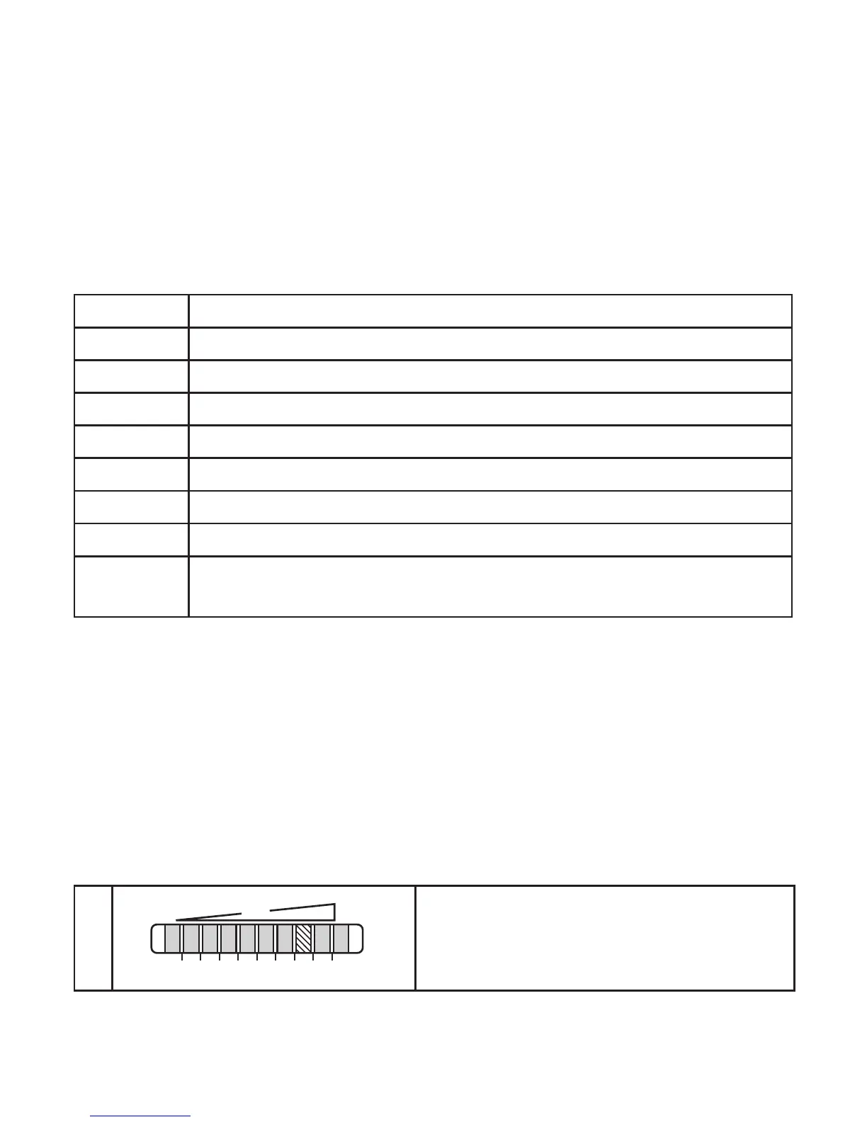
SP1 / rP1 Upper / lower limit value for flow at which OUT1 switches
SP2 / rP2 Upper / lower limit value for flow at which OUT2 switches
OU1 Output configuration OUT1 (flow)
OU2 Output configuration OUT2 (temperature)
Set_High Reading of the maximum flow (100 %)
Set_Low Reading of the minimum flow (0 %)
dS1 / dr1 Switch-on delay / switch-off delay for OUT1
dS2 / dr2 Switch-on delay / switch-off delay for OUT2
Loc Locks sensor operation to prevent unintentional maladjustment�
Can be reset on the unit�
7.2 Set-up and settings for water
Formediaotherthanwater→7.6Low-flowadjustment(optional).
► Switch on the supply voltage�
> All LEDs light and go out again step by step� During this time output OUT1 is
closed (if configured as normally open)� The unit is in the operating mode�
► Let the normal flow circulate in the installation�
► Check the display and determine further actions�
1
The factory setting is suitable for the applica-
tion�
► For flow monitoring no further settings are
required�



 To Next Page