13
UK
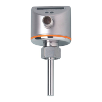
After LED 0 has been reached the cycle of the flashing LED starts again at
LED 9; the continuously lit LED (tens digit) moves one position to the left (when
setting is made with )�
5 s after the last press of the pushbutton the display returns to the tem-
perature and switch point display mode (step 1)� After another 5 s the unit
returns to the operating mode with the newly set value�
7.6 Low-flow adjustment (optional)
If the unit is used in media other than water, you should additionally adapt the unit
to the minimum flow�
The following adjustment must only be carried out after the high-flow
adjustment�
Proceed as follows:
► Let the minimum flow circulate in the installation or ensure flow standstill�
► Press and keep it pressed�
> LED 0 lights, after approx� 5 s it flashes�
► Release the button� The unit adopts the new value and returns to the operating
mode�
7.7 Configuration of the switching outputs (optional)
The unit is delivered as normally open� If necessary you can change the outputs to
normally closed function� The setting applies to both outputs�
► Press for at least 15 s�
> LED 0 lights, after approx� 5 s it flashes�
> After 10 s the current setting is displayed: LEDs 5���9 light orange (= outputs
normally open)�
> After approx� 15 s LEDs 0���4 flash orange�
► Release the button� The outputs are changed to normally closed function�
For a new changeover: repeat the operation�
 Loading...