16
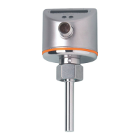
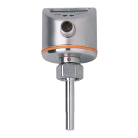
8.3 Interference indicators
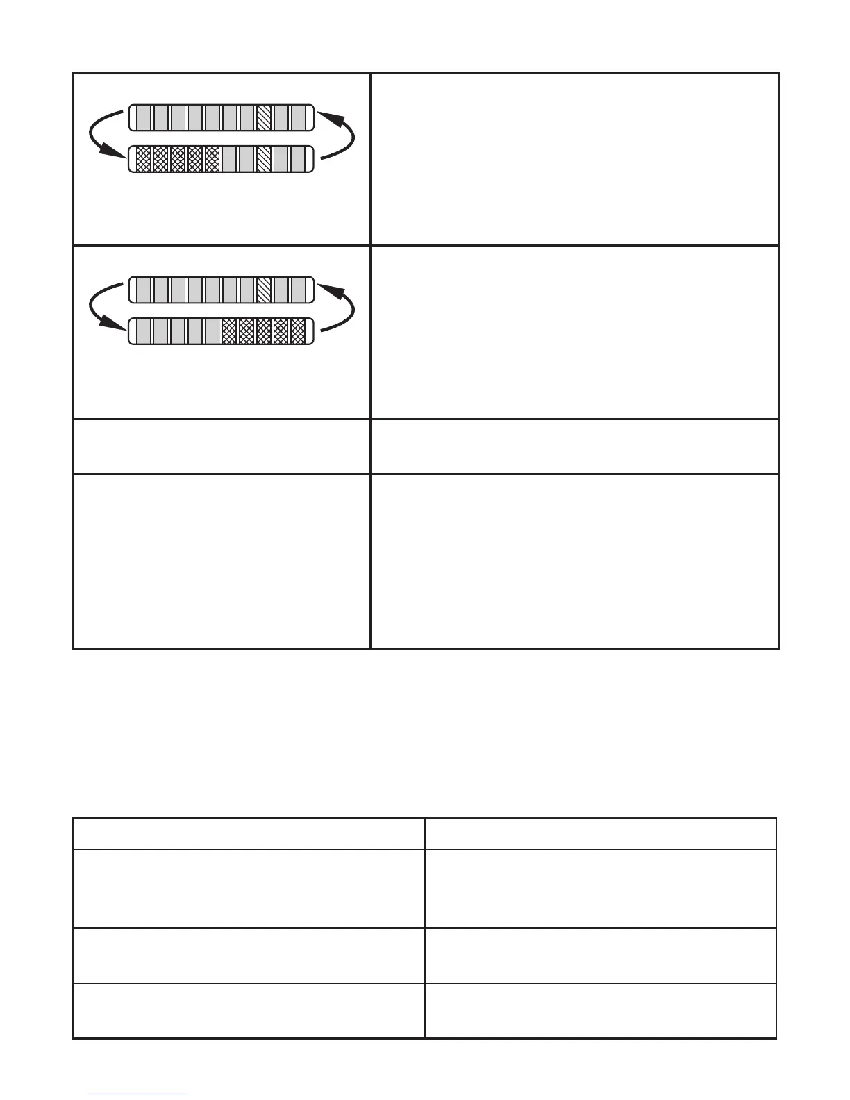
Short circuit at switching output OUT1�
The operating indicator and 5 red LEDs on the left
light alternately�
If the short circuit has been rectified, the unit imme-
diately passes into the normal operating state�
The current operating state is displayed�
Short circuit at switching output OUT2�
The operating indicator and 5 red LEDs on the right
light alternately�
If the short circuit has been rectified, the unit imme-
diately passes into the normal operating state�
The current operating state is displayed�
Display OFF
(no LED lights):
Operating voltage too low (< 19 V) or failed�
Ensure a correct voltage supply�
Display briefly OFF
(LEDs go off when a button is
pressed)
The active LEDs go off briefly when a button is
pressed if
- an IO-Link communication is active (temporary
locking)
- orthesensorispermanentlylocked(→7.9).
After approx� 0�6 seconds the last operating state
is displayed�
9 Troubleshooting
Ifhigh-flowadjustment(→7.3)orlow-flowadjustment(→7.6)isnotpossible,
all LEDs flash red� The unit then returns to the operating mode with unchanged
values�
Possible causes Corrective measures
Error during installation of the flow sensor�
► Readchapter→4Installation.Check
whether all requirements have been
met�
The difference between maximum flow and
minimum flow is too small�
► Increase the flow difference and carry
out the adjustment again�
The sequence high-flow / low-flow adjust-
ment was not adhered to�
► Carry out the two adjustment operations
again in the right sequence�
 Loading...