CompactModul Metall CR2033
6
5 Electrical connection
To guarantee the electrical interference protection of the module, the hous-
ing must be connected to GND (e�g� to the ground of the vehicle)�
Due to the maximum operating temperature of 85 °C and the internal heat-
ing of the unit, the respective minimum rated temperature of the connection
cable must be taken into account�
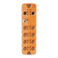
5.1 M12 sockets
Use sockets with gold-plated contacts�
Use protective caps (supplied) for unconnected connectors of the I/O module�
5.2 Tightening torque of the cover screws (terminal chamber)
To close the terminal chamber the cover screws are tightened with a tightening
torque of 1�2 Nm�
5.3 M16 cable gland
Use a suitable cable to ensure ingress resistance of the M16 cable gland�
If the M12 connectors are used for the device supply and CAN connection, close
the terminal chamber with the supplied M16 cover plug (remove the cable gland
and insert the M16 cover plug)�
5.4 Definition of short-circuit and overload protection
● Short-circuit test:
All outputs must withstand a short-circuit current limited to 60 A flowing be-
tween output and ground (GND) or supply voltage (+VBB)�
Test duration: 3 minutes
● Overload test:
Outputs must not be destroyed by a 100 % overload�
(e.g. nominal switching current IN = 4 A → 100 % overload = 8 A)
Test duration: 5 minutes
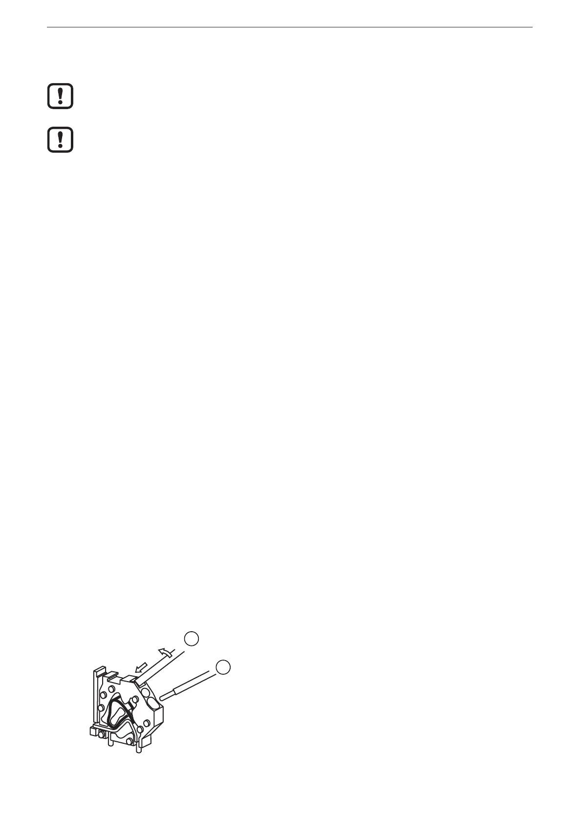
5.5 CAGECLAMP ® connection technology
1
2
1: Screwdriver
2: Wire
► Insert screwdriver an tilt slightly�
> Spring opens�
► Insert wire�
► Remove screwdriver�
> Spring closes�