CANwireless CR3133
11
8 Set-up
8.1 Necessary components
The following components are needed to configure and set up the device:
• Hardware
– CR3133
– suitable antenna (e.g. article no. EC3133)
– connection cable
– voltage supply 8…32 V DC
– PC / notebook
– CAN/ PC interface (e.g. CAN/RS232-USB interface CANfox, art. no. EC2112) and adapter
cable for CANfox (art. no. EC2113) with CAN bus terminating resistors (2 x 120 Ω)
• Configuration software
– ifm Maintenance Tool
– mobileIoT device configuration addin for ifm Maintenance Tool
For details on how to configure the device, see the ifm Maintenance Tool documentation.
8.2 Connecting the device
u Connect the antenna to the device.
u Ensure that the CAN bus is provided with 120 Ω terminating resistors.
u Connect the CAN/PC interface with the CAN adapter cable to the device and connect it to the PC.
u Connect the ground terminal of the power supply to CAN1-GND.
u Apply the supply voltage.
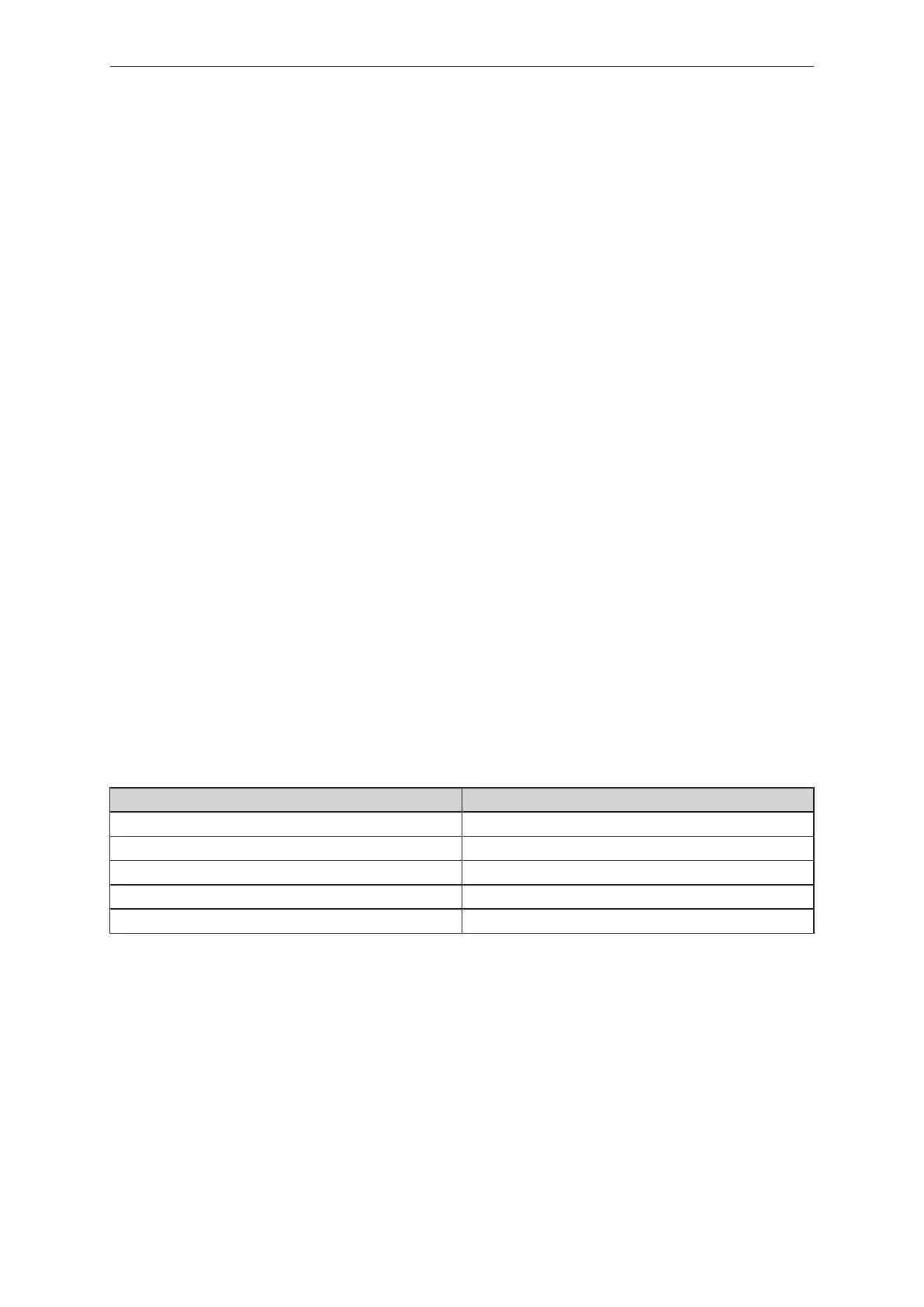
The following table provides an overview of some CAN baud rates in relation to the cable length:
CAN baud rate Cable length CAN bus
800 kbit/s 50 m
500 kbit/s 100 m
250 kbit/s 250 m
125 kbit/s 500 m
50 kbit/s 1000 m
Tab.3: CAN baud rate
8.3 Configuration
This chapter describes the configuration of the CANwireless device. The setup of the CAN interface
and the settings of the different operating modes are presented.
8.3.1 CANopen
By default, the device is configured to receive CANopen messages such as Tx SDOs, Rx SDOs and
error messages (EMCY). The device processes the messages without forwarding them via the
wireless interface.
With the following object, this behaviour can be adjusted: