UK
ecomatController CR710S/CR711S
9
5 Electrical connection
5.1 Wiring
Wiring (→ 7 Technical data)
Only connect the connector pins as shown in the pin layout�
Unspecified connector pins remain unconnected�
► Connect all indicated supply cables and GND terminals�
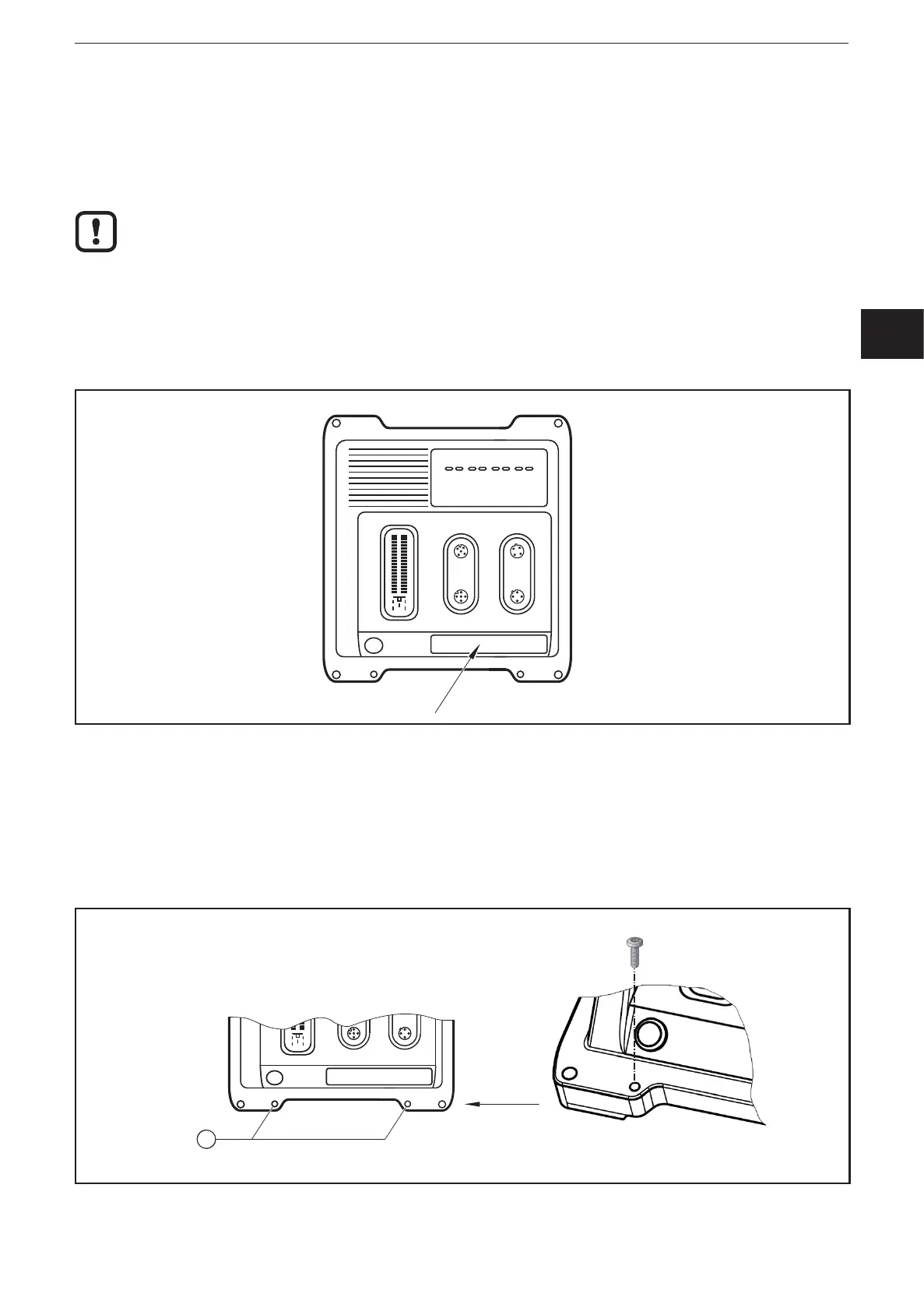
5.1.1 Assignment of the connectors
► Note the device label�
EPS Source
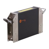
Product Scale Drawing
Frame Size: 80 mm x 49,5 mm
Original Scale Drawing (MTD)
P_MZ_e100_0094
Scale: 1:2
18
47
206
219
182
203
6,4 M12x1
LEDs
1
Assignment of the connectors on the device label
► Use the M12 connector with gold-plated contacts�
► Unused sockets are equipped with protective caps (included)�
► For protection rating IP 67, use a device with individually sealed cores�
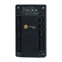
5.2 Shield connection
EPS Source
Product Scale Drawing
Frame Size: 80 mm x 49,5 mm
Original Scale Drawing (MTD)
P_MZ_e100_0093
Scale: 1:2
18
47
206
219
250
271
6,4 M12x1
LEDs
1
2
1
1
1: Holes for shield connection
 Loading...