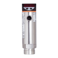
This document provides operating instructions for the ifm PN422x series pressure sensor, a subcomponent designed for integration into a larger system. The device is intended for detecting system pressure and providing an output signal based on set limits.
Function Description
The PN422x pressure sensor measures the system pressure and displays it on a 7-segment display. It generates one output signal (OUT1) based on a user-configured switching function. This output signal is primarily used for system pressure limit values. The sensor supports relative pressure measurement.
Switching Functions (OUT1):
The output OUT1 changes its switching state when the system pressure is above or below the set switching limits (SP1 and rP1).
- Hysteresis Function:
- Normally open:
[OU1] = [Hno]
- Normally closed:
[OU1] = [Hnc]
For hysteresis, the set point (SP1) is configured first, followed by the reset point (rP1) with the desired difference.
- Window Function:
- Normally open:
[OU1] = [Fno]
- Normally closed:
[OU1] = [Fnc]
For window functions, SP1 represents the upper value and rP1 the lower value, defining the width of the window.
Important Technical Specifications
- Pressure Measurement: Relative pressure.
- Output Signal: 1 switching signal (OUT1).
- Measuring Range: Units with a final value of 1...400 bar comply with section 3, article (3) of Directive 97/23/EC for group 2 fluids (stable gases and non-superheated liquids).
- Overpressure Protection: Avoid static and dynamic overpressure exceeding the specified overload pressure. The indicated bursting pressure must not be exceeded. Exceeding bursting pressure, even briefly, can destroy the unit and poses a risk of injury.
- Gases at High Pressure: Use in gases at pressures > 25 bar only on request.
- Display Range: Indication of current system pressure starts from 1% of the final value of the measuring range. "0%" display does not necessarily mean no pressure is applied.
- Electrical Connection:
- Must be connected by a qualified electrician, adhering to national and international regulations.
- Output circuit requires protective measures similar to the supply circuit, including a miniature fuse (IEC60127-2 Sheet 1, 5 A fast acting).
- Permissible potential difference between supply and output circuit: max. 300 V.
- Equalization of potential for metal housing parts must be ensured via the sensor housing, requiring an electrically conductive connection. A grounding clamp (order no. E43321) is available for this purpose.
- Integrated EMC filters may cause leakage currents of typ. < 0.5 mA to flow via potential equalization to earth. These currents add up if multiple units are used in parallel.
- Touchable surfaces are insulated (double or reinforced insulation according to IEC 61010-1) to overvoltage category III, rated operating voltage 300 VAC.
- Grounding Clamp (E43321): Designed to discharge noise voltages when the sensor is mounted to ungrounded installations (e.g., plastic pipes). It should be used preferably on PN42xx series sensors. The earthing strap and clamping device must contact the sensor sleeve outside the type label area.
Usage Features
Installation:
- Ensure no pressure is applied to the system before installing or removing the unit.
- Insert the unit into a suitable process connection with a thread.
- Tighten firmly. For 1/4-18 NPT threads, tighten 2-3 turns after finger-tightening, using sealants and lubricants for leak-free joints.
- If installed in an ungrounded pipe system, the unit must be grounded using the grounding clamp.
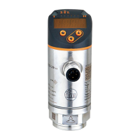
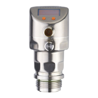
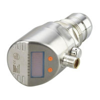
Operating and Display Elements:
- 7-segment display (1): Shows current system pressure, parameters, and parameter values. For PSI values > 999, the displayed value is multiplied by 10.
- LED red (2): Indicates switching status; lights when the output is switched.
- Set button (3): Used to set parameter values (scrolling by holding, incremental by brief presses).
- Mode/Enter button (4): Selects parameters and acknowledges parameter values.
Parameter Setting:
The unit remains in operating mode during parameter setting, continuously monitoring with existing parameters until setting is complete.
- Parameter Selection: Press
[Mode/Enter] until the desired parameter is displayed.
- Setting Parameter Value: Press and hold
[Set]. The current value flashes for 5 seconds, then changes incrementally with brief presses or continuously with a long press. Numerical values increment continuously; to decrease, let the display cycle to the maximum value, then it restarts from the minimum.
- Acknowledgement: Briefly press
[Mode/Enter] to save the new setting.
- Changing Menu Levels: To access extended functions (menu level 2), press
[Mode/Enter] until [EF] is displayed, then briefly press [Set].
- Locking/Unlocking: To prevent unintentional settings, the unit can be locked electronically. In normal operating mode, press
[Mode/Enter] + [Set] for 10 seconds until [Loc] is displayed. Repeat to unlock. If locked, [Loc] briefly displays when attempting to change values.
- Timeout: If no button is pressed for 15 seconds during parameter setting, the unit returns to operating mode with unchanged values.
User Settings (Optional):
- Unit of Measurement (
[Uni]): Select [bAr] (bar/mbar), [PA] (MPa/kPa), [inH] (inHg), or [PSI]. For PSI ranges > 999, the displayed value is 1/10th of the real value. Stickers are provided for different units and correction factors.
- Display Configuration (
[diS]):
[d1]: Update every 50 ms.[d2]: Update every 200 ms.[d3]: Update every 600 ms.[Ph]: Peak hold (displays pressure peaks briefly).[rd1], [rd2], [rd3], [Ph]: Same as above, but display rotated by 180°.[OFF]: Display is switched off in operating mode.
- Zero-Point Calibration (
[COF]): Set a value between -5% and 5% of the final measuring range value to shift the internal "0" point.
- Zero-Point Calibration Reset (
[CAr]): Press [Mode/Enter] until [CAr] is displayed, then press and hold [Set] until [---] is shown, then briefly press [Mode/Enter].
- Delay Time for OUT1 (
[dS1]/[dr1]): Set switch-on ([dS1]) or switch-off ([dr1]) delay between 0.1 and 50 seconds. 0.0 means no delay.
- Damping for OUT1 (
[dAP]): Set a value between 0.01 and 4.00 seconds. 0.00 means no damping. dAP is the response time between pressure change and switching status change, influencing switching frequency (fmax = 1 + 2dAP).
Service Functions:
- Read Min/Max Values (
[HI]/[LO]): Select [HI] (maximum) or [LO] (minimum) and briefly press [Set] to view.
- Delete Memory: Select
[HI] or [LO], press and hold [Set] until [---] is displayed, then briefly press [Mode/Enter].
Operating Indicators:
- In Run mode (normal operating mode) after power-on, the unit performs measurements, evaluations, and provides output signals according to set parameters.
- Reading Set Parameters: Briefly press
[Mode/Enter] to cycle through parameters. Briefly press [Set] to display the corresponding value for ~15 seconds. After another 15 seconds, the unit returns to Run mode.
Maintenance Features
- Error Indications:
[OL]: Overload pressure (above measuring range).[UL]: Underload pressure (below measuring range).
- General Safety: Installation, electrical connection, set-up, programming, configuration, operation, and maintenance must be carried out by qualified and authorized personnel. Protect units and cables against damage.
- The product must be suitable for the corresponding applications and environmental conditions without restrictions.
- Only use the product for its intended purpose and with permissible media.
- Non-compliance with operating instructions or technical data can lead to personal injury and/or property damage.
- The manufacturer assumes no liability for consequences caused by tampering or incorrect use.
Factory Setting (PN422x):
SP1: 25% VMR (Value of Measuring Range)rP1: 23% VMROU1: Hno (Hysteresis normally open)COF: 0.0 (Zero-point calibration)dS1: 0.0 (Switch-on delay)dr1: 0.0 (Switch-off delay)dAP: 0.06 (Damping)diS: d2 (Display update rate)Uni: bAr / mbAr (Unit of measurement)