Do you have a question about the IFM PN72 Series and is the answer not in the manual?
Explanation of symbols used in the manual for instructions, reactions, and notes.
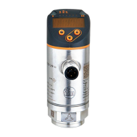
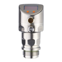
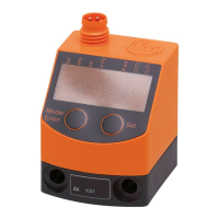
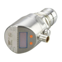
Details on pressure sensors, including order numbers, measuring ranges, overload, and bursting pressure ratings.
Description and applications for Operating Mode 1 (compatibility) and Operating Mode 2 (standard applications).
Overview of communication options, parameter setting, and data evaluation via OUT1, OUT2, and IO-Link.
Explanation of hysteresis and window functions for switching outputs, including normally open and normally closed modes.
General information on IO-Link interface, required hardware, and functions available via IO-Link communication.
Diagram illustrating the main menu structure and navigation flow within the device's interface.
Detailed explanation of menu level 1 parameters like SPx, rPx, FHx, FLx, EF and menu level 2 parameters.
Step-by-step guide for selecting, setting, and acknowledging parameter values using the device buttons.
Procedure for electronically locking and unlocking the device to prevent unintentional parameter changes.
Instructions for selecting and setting the operating mode (1, 2, or 3) and its implications.
Steps to configure the display unit of measurement (bar, psi, etc.) and update rate/orientation.
Configuration of output functions (hysteresis, window) and switching limits for OUT1 and OUT2.
Optional user settings including delay time, logic, damping, colour change, and parameter reset.
Functions for reading minimum/maximum pressure values and overload processes (HIPC, HIPS).
Instructions on how to read currently set parameters on the device display.
Information on device self-diagnostics, fault/warning indications, and corresponding corrective measures.
Details on permissible setting ranges (rP/SP, cFL/cFH) for various models in operating modes 2 and 3.
Reference to additional technical data and scale drawings available on the manufacturer's website.
| Brand | IFM |
|---|---|
| Model | PN72 Series |
| Category | Accessories |
| Language | English |