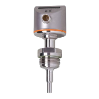
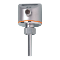
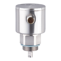
The SI0558 and SI0564 are flow monitors designed to detect and monitor the flow of liquids and gases based on the calorimetric measuring principle. These devices provide an output signal that switches based on the detected flow, and their switch point is adjustable to suit various application requirements.
Function Description:
The flow monitor continuously monitors the flow of media. When the flow reaches the adjustable switch point, the device's output switches. The typical response time of the device ranges from 1 to 10 seconds, which can be influenced by the switch point setting. A low switch point results in a quick reaction to rising flow, while a high switch point leads to a quick reaction to falling flow. The device is a subcomponent intended for integration into a larger system, and the system architect is responsible for ensuring the overall safety of the system.
Important Technical Specifications:
Detailed technical data, approvals, and further information for the SI0558 and SI0564 can be found by scanning the QR code on the unit/packaging or by visiting www.ifm.com. The device operates with a supply voltage, and its electrical connection requires a qualified electrician to ensure compliance with national and international regulations. A miniature fuse (≤ 5 A fast acting) according to IEC 60127-2 Sheet 1 must be inserted for the output circuit. The minimum immersion depth for the sensor tip is 12 mm, ensuring it is completely surrounded by the medium.
Usage Features:
- Installation:
- Immersion Depth: The sensor tip must be fully immersed in the medium, with a recommended minimum immersion depth of 12 mm.
- Mounting Position:
- Recommended: For horizontal pipes, mounting from the side is recommended. For vertical pipes, mounting in the rising pipe is preferred.
- Conditionally Possible: For horizontal pipes, mounting from below is possible if the pipe is free from build-up. Mounting from the top is possible if the pipe is completely filled with the medium.
- Impermissible: Installation in areas where the sensor tip is not in contact with the pipe wall or in downpipes that are open at the bottom is not allowed.
- Interference: Structures like pipes, bends, valves, and reducing pieces can affect the function of the unit. Adherence to recommended distances (e.g., 5 x D upstream and 3.5 x D downstream, where D is the outside diameter of the pipe) from such structures is crucial to minimize interference.
- Process Connection: The unit can be adapted to different process connections using process adapters. For small flow rates, ifm adapter blocks are available. When connecting, ensure the threads are greased with a suitable lubricant, and tighten the coupling nut to 25 Nm, ensuring correct orientation.
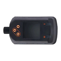
- Operating and Display Elements:
- The device features an LED bar (0-9) that indicates the range of the monitored flow, with green LEDs showing the current flow.
- An illuminated LED indicates the position of the switching point: orange for output closed, red for output open.
- Setting buttons ([–] and [+]) are used for adjustment and configuration.
- Set-up: Upon switching on the supply voltage, all LEDs light up and then go out step by step, during which time the output is closed. The device then enters operating mode.
- Settings:
- Switch Point Setting: The switch point can be adjusted by briefly pressing [–] or [+]. Each press shifts the flow by half an LED in the indicated direction. The LEDs of the current process value flash during adjustment. After setting, the device returns to operating mode with the new value.
- Teaching the Switch Point: The switch point can be set to the current flow value. With the required flow passing through the installation, press the [–] button for at least 15 seconds. LEDs 0 and 9 will first light up green, then flash green. Releasing the button sets the new value, and the unit returns to operating mode. LEDs to the left of the switch point light green, and the switch point LED lights red.
- Restoring Factory Settings (Reset): Press the [+] button for at least 15 seconds. All LEDs will first light up orange, then flash orange. Releasing the button resets all settings to the factory default, and all LEDs go off for 2 seconds.
- Lock/Unlock: The unit can be electronically locked to prevent unauthorized changes. This is done by pressing both setting keys simultaneously for 10 seconds until the display goes off. Repeating this process unlocks the unit.
- Operation: After power-on, the unit is ready for operation. The output (LED yellow) closes if the flow is greater than or equal to the switch point, and the output (LED red) opens if the flow quantity is less than the switch point. In case of power failure or interruption of the operating voltage, all settings remain.
Maintenance Features:
- Only the manufacturer is authorized to repair the unit.
- Regularly check the sensor tip for build-up. It is recommended to check one month after set-up and then at intervals determined by the application.
- To clean a soiled sensor tip, use a soft cloth. For stubborn build-up, a common vinegar cleaning agent can be used.
- After its service life, the device must be disposed of in an environmentally friendly manner in accordance with applicable national regulations.
Troubleshooting:
- Display OFF briefly (LEDs go off when a button is pressed): Indicates the sensor is permanently locked. Unlock the unit using the lock/unlock procedure.
- Display OFF (no LED on): Indicates operating voltage is too low (< 19 V) or has failed. Ensure correct voltage supply.
- Automatic adjustment not successful (switch point outside measuring range): Check flow and installation, then repeat the switch point teaching procedure if necessary.