Flow monitor SI0558 SI0564
7
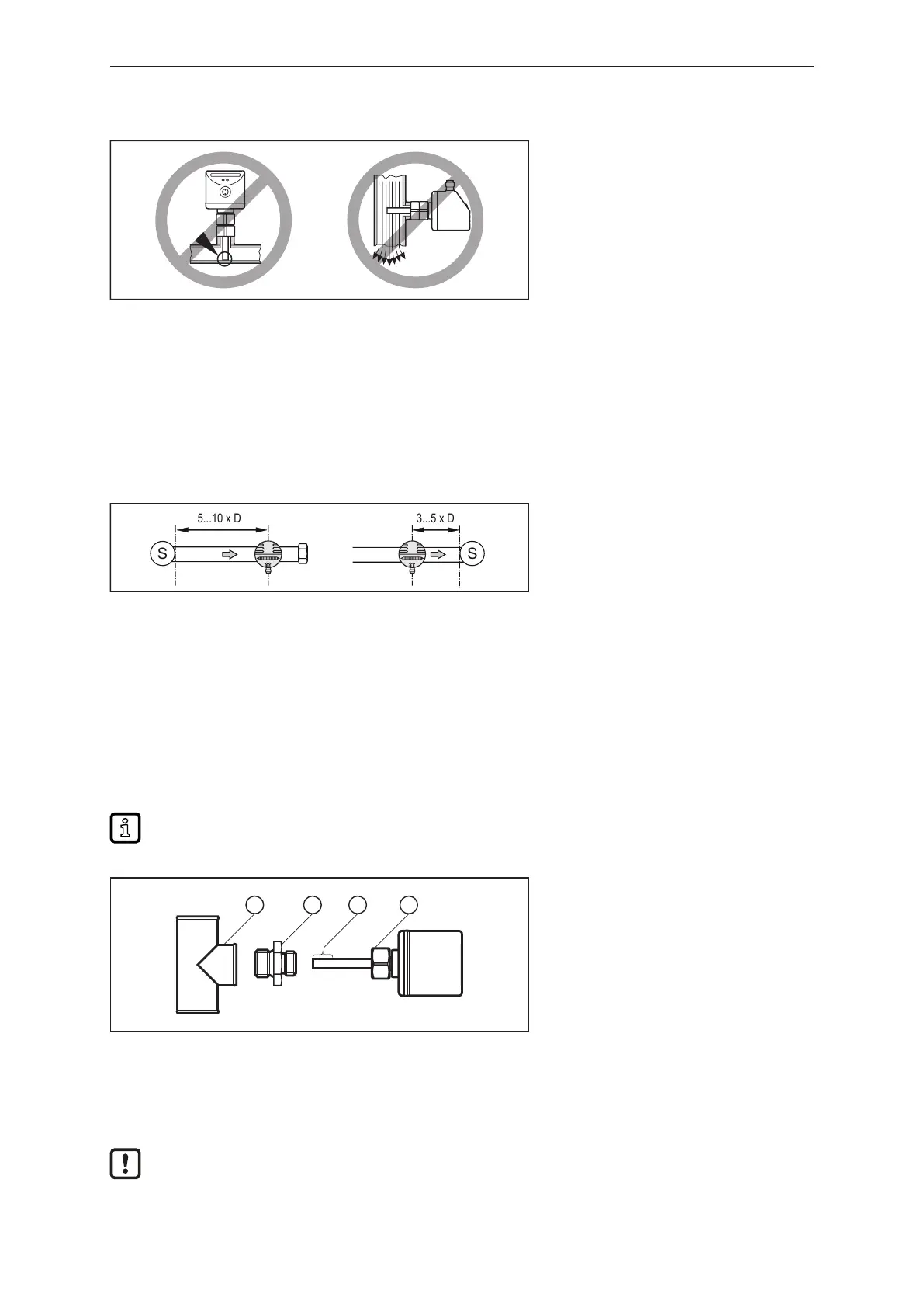
4.1.4 Impermissible installation position
Fig.4: Impermissible installation position
• The sensor tip must not be in contact with the pipe wall.
• Do not mount in downpipes that are open at the bottom.
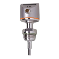
4.2 Interference
Structures in the pipe, bends, valves, reducing pieces and the like affect the function of the unit.
u Adhere to the distances between sensor and interference.
Fig.5: Inlet and outlet pipe lengths
D: Outside diameter of the pipe
S: Interference
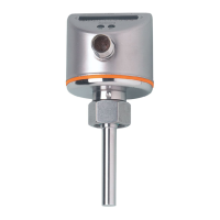
4.3 Process connection
Using process adapters the unit can be adapted to different process connections.
A correct fit of the unit and ingress resistance of the connection are only ensured using ifm adapters.
For small flow rates, ifm adapter blocks are available.
The device is supplied without accessories.
Information about available accessories at documentation.ifm.com.
The optimum function is not ensured when using components from other manufacturers.
Fig.6: Connect the device to the process using the adapter
1: Process connection 2: Adapter
3: Sensor tip 4: Coupling nut
u Grease the threads of the process connection, adapter and sensor. Use a lubricating paste which
is suitable and approved for the application.
Ensure no grease is applied to the sensor tip.
u Screw the suitable adapter into the process connection.