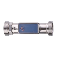
This document provides operating instructions for the SU2020, SU8020, SU2021, SU8021, SU2621, and SU8621 ultrasonic flow meters. These devices are designed to monitor liquid media, specifically conductive water-based media and non-conductive water. They detect flow velocity, volume flow (volumetric flow quantity/time), consumed quantity, and medium temperature.
Function Description
The ultrasonic flow meter operates based on the measuring principle of ultrasonic transit time difference to detect volumetric flow. It continuously displays the current process values and incorporates self-diagnostic options for monitoring flow direction and signal quality. The unit also indicates warnings and error messages. All self-diagnostic options, including the color signal of an operating status LED, diagnostic information, and outputs, are provided via the IO-Link interface. A simulation mode is available for simplified setup of the sensor.
The device offers various output options:
- Output 1 (OUT1): Can be configured for switching signal flow, switching signal temperature, switching signal diagnosis, direction of flow, signal quality, switching signal totaliser, pulse signal totaliser, frequency signal flow, frequency signal temperature, and IO-Link. It can also be switched OFF (output switched to high impedance).
- Output 2 (OUT2): Similar to OUT1, it can be configured for switching signal flow, switching signal temperature, switching signal diagnosis, direction of flow, signal quality, switching signal totaliser, pulse signal totaliser, analogue signal flow, analogue signal temperature, and input for external totaliser reset. It can also be switched OFF (output switched to high impedance).
IO-Link is a communication system for connecting intelligent sensors and actuators to automation systems, standardized in IEC 61131-9. IO-Link offers several advantages:
- Interference-free transmission of all data and process values.
- Parameter setting in the running process or presetting outside the application.
- Parameters for identifying the connected devices in the system.
- Additional parameters and diagnostic functions.
- Automatic backup and restore of parameter sets in case of device replacement (data storage).
- Logging of parameter sets, process values, and events.
- Device description file (IODD - Input Output Device Description) for easy project planning.
- Standardized electrical connection.
- Remote maintenance.
Important Technical Specifications
The unit is designed for liquid media, specifically conductive water-based media and non-conductive water. It complies with the Pressure Equipment Directive (PED) for group 2 fluids in accordance with sound engineering practice.
Installation:
- The medium temperature must be above 50 °C (122 °F); otherwise, the housing temperature may increase to over 65 °C (149 °F), posing a risk of burns.
- Protect the housing against contact with flammable substances and unintentional contact.
- Ensure the system is free of pressure during installation and operation of compressed air equipment.
- No functional earthing is required in an ungrounded pipe system (e.g., plastic pipes).
- The device has a deficient operating function if not properly grounded. Ground brackets for the M12 connector are available as accessories.
- The optimum function is ensured when using components from other manufacturers.
- For SU8621, use hexagons on both sides of the unit for fixing.
- Sensor damage can occur if tightening torques higher than 50 Nm are applied. Use a screwing tool that allows setting a fixed tightening torque.
- After installation, air bubbles in the system can affect measurements. Corrective measures include rinsing the system after installation for ventilation.
Recommended Installation Position:
- Install the unit so that the measuring pipe is always completely filled.
- Install in front of or in a rising pipe.
- No air bubbles can form in the pipe system; the pipes must always be completely filled.
Non-recommended Installation Position:
- Directly in front of a falling pipe.
- In a falling pipe.
- Directly in front of the spout of a pipe.
- Directly in front of a valve.
- On the suction side of a pump.
- At the highest point of the pipe system.
Electrical Connection:
- The unit must be connected by a qualified electrician.
- Observe national and international regulations for the installation of electrical equipment.
- Voltage supply according to SELV, PELV.
- Disconnect power before connecting.
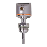
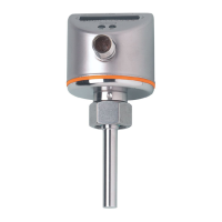
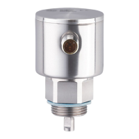
Operating and Display Elements:
- Switching status LED for OUT1 (1): Lights yellow if output 1 is switched.
- Switching status LED for OUT2 (2): Lights yellow if output 2 is switched.
- Operating status LED (3): Lights green, blue, or red.
- TFT display (4): Shows title line (4a) and process value line (4b).
- Keys (5): Used for changing views and parameter settings.
- If the unit measures a high internal temperature (over 64 °C), display brightness is reduced to 25%. If the internal temperature is 90 °C or higher, the display automatically switches off.
Usage Features
The device features a menu structure for setting parameters. The main menu includes:
- Process value display
- Extended functions (EF)
- OUT1 configuration [OUT1]
- OUT2 configuration [OUT2]
- Basic settings [CFG]
- Totaliser [TOTL]
- Display settings [DIS]
- Diagnostic indicators [DIAG]
- Simulation mode [SIM]
- Device info [d.InF]
- Reset device [rES]
Guided Installation:
A guided installation wizard simplifies the initial setup.
- Select [Yes] or [No] for guided installation.
- If [Yes] is selected, parameters, questions, and instructions appear on the screen. Use the [▲] and [▼] keys to choose from available options and the [◄] key to confirm the selection.
- If [No] is selected, the main menu appears, and sensor functions are set to factory settings.
- The guided installation can be called up at any time via the parameter [EF] > [CFG] > [Guide].
During guided installation, the following settings appear in succession:
- [diS.R]: display rotation
- [LanG]: display language
- [Fdir]: flow direction
- Output OUT1:
- [SEL1]: process value (flow or temperature) or diagnosis (flow direction or signal quality).
- [uni.T] / [uni.F]: standard unit of measurement.
- [ou1]: switching signal (Hno, Hnc, Fno, Fnc), pulse signal/switching signal totaliser, frequency signal.
- Configuration of parameters for [ou1]: limit values for switching signal: SP1, rP1, FH1, FL1; pulse values for totaliser: ImPS; switch point and reset for totaliser: ImPS1, rTo1; limit values for frequency signal: FSP1 (only for temperature), FEP1, FrP1.
- [FOU1]: error behaviour of the output.
- Output OUT2:
- [SEL2]: process value (flow or temperature) or diagnosis (flow direction or signal quality).
- [uni.T] / [uni.F]: standard unit of measurement.
- [ou2]: switching signal (Hno, Hnc, Fno, Fnc), pulse signal/switching signal totaliser, analogue signal.
- Configuration of parameters for [ou2]: limit values for switching signal: SP2, rP2, FH2, FL2; pulse values for totaliser: ImPS2, rTo2; switch point and reset for totaliser: ImPS2, rTo2; limit values for analogue signal: ASP2, AEP2.
- [FOU2]: error behaviour of the output.
- [diS.L]: display layout.
After the guided installation is completed, the unit changes to the process value display.
Parameter Setting:
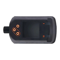
Parameters can be set via the IO-Link interface or using the operating elements on the unit.
- Changes to parameters during operation can influence the function of the plant.
- Ensure that there will be no malfunctions in your plant.
- Parameter setting remains in the operating mode. It continues to monitor with the existing parameter until the parameter setting has been completed.
- Depending on the parameter setting, the parameters available in the menu may change.
Display Settings:
- Display language (LanG): Selectable languages include German, English, Spanish, French, Italian, Japanese, Korean, Portuguese, Russian, and Chinese.
- Display rotation (diS.R): Selectable values are 0° (not rotated), 90°, 180°, and 270°.
- Display brightness (diS.B): Selectable values are 25%, 50%, 75%, and 100%.
- Display update rate (diS.U): Selectable values are d1: fast, d2: medium, d3: slow.
- Display layout (diS.L): Choose which process values are shown by default. Selectable values include L1 (current process value for flow), L2.Tem (current process value for flow and temperature), L2.Totl (current process value for flow and totaliser Vol.1), L3 (current process value for flow and temperature and totaliser Vol.1), and L4 (current process value for flow and temperature and totaliser Vol.1 and signal quality).
- Display color setting (col.x): Font color can be set for flow, temperature, and totaliser Vol.1. Color change can be configured for the displayed flow and temperature depending on the current process value.
Maintenance Features
Diagnostic Functions:
Diagnostic messages are provided via an output signal. This chapter describes diagnostic functions that provide information but not an output signal.
- Read totaliser values: For totalisers Vol.1 and Vol.2, the following values can be read at any time: current volumetric flow quantity (= consumed quantity since the last reset), consumed quantity before the last reset, and time in minutes since the last reset. For totaliser Vol.L, the following values can be read at any time: volumetric flow quantity in preferred direction (= positive flow direction) and volumetric flow quantity in non-preferred direction (= negative flow direction).
- Memory: The unit stores the maximum and minimum measured process values. It is recommended to delete the memories as soon as the unit operates under normal operating conditions for the first time.
- Operating hours counter: The operating hours since the first set-up are stored by the unit.
- Internal temperature: The sensor measures the internal temperature. A high internal temperature is signaled by the unit as a warning via the operating status LED.
- Signal quality: The signal quality of the sensor can be affected by irregularities in the medium (e.g., strong turbulences, air bubbles, particles, or build-up). The unit detects signal quality in three stages:
- Normal: Unit operates without restrictions (normal operation), LED lights green.
- Low: Signal quality is disturbed, but the unit is still working within its specifications, LED lights blue.
- No signal: No medium is present or no signal can be created, LED flashes red.
- Operating status LED: The unit has an operating status LED that indicates deviations from normal operation (= diagnostic cases) by a color signal. The function of the operating status LED is adjustable.
- Simulation: Process values that lead to an error message or warning can be simulated (e.g., OL: process value above the measuring range). When the simulation is started, the values of the totaliser are frozen, and the simulated totaliser is set to 0. The simulated flow value then has an effect on the simulated totaliser. When the simulation is ended, the initial totaliser values are restored.
- The simulation has no effect on the current process values.
- The outputs operate as previously set.
- The original totaliser value remains saved without any changes even if there is a real flow.
- No error messages of the current application are available.
- The following values can be simulated: process values for flow and temperature, process values outside the measuring range (cr.UL, UL, OL, cr.OL).
Identification:
- Device information: Unalterable device information is stored on the unit. This includes: Product name, Product family, Manufacturer, Manufacturer ID, Device ID, Serial number, Hardware / firmware revision, Description. Additionally, freely definable tags (up to 32 characters) can be assigned via the IO-Link interface using parameter setting software. These include: application-specific tag, function tag, location tag.
- Optical localisation: The sensor can be located remotely in the system via the IO-Link interface. When the command is used, the switching status LEDs will flash, and the IO-Link LED will flash on the display.
Troubleshooting:
The unit has many self-diagnostic options. It monitors itself automatically during operation. Warnings and error messages are displayed even if the display is switched off. Error indications are also available via IO-Link. The status signals are classified according to NAMUR recommendation NE107. If several diagnostic events occur simultaneously, only the diagnostic message of the event with the highest priority is displayed. In addition, warnings and error messages are displayed by the unit as follows:
- Switching signal when using OUT1 or OUT2 as diagnostic output.
- Color signal of the operating status LED.
If the measured temperature value fails, the process value for flow rate is still available. Additional diagnostic functions are available via IO-Link.
Warning Messages:
- Display off: Problem/remedy includes supply voltage too low, check supply voltage, display switched off, check whether [diS.B] is OFF and change setting if necessary, operating status LED switched off, check whether [LED.M] is OFF, and change setting if necessary.
- Internal unit temperature too high: Slow unit to cool down.
- Title line: Short circuit OUT1/OUT2: Short circuit in both outputs, check OUT1 and OUT2 for short circuit or excessive current.
- Title line: Over limit/Under limit: Check the measuring range.
- Title line: Override active: A process value differs from the measured value. Set to 0 or write over. Title bit is set in PDOout. Deactivate PDOoverride.
- Title line: Signal quality low: Signal quality low, remove unit and check for deposits, check application for interference (air bubbles/particles).
- Title line: IO-Link: IO-Link function for optical identification of the active unit. Deactivate IO-Link function.
- Title line: Simulation: Simulation active. End simulation.
- Title line: Lock via key/system/communication: Setting keys on the unit locked, parameter change rejected. Unlock the unit using the keys or IO-Link interface. Finish parameter setting via IO-Link communication.
Error Messages:
- Title line: Hardware error: Unit faulty/malfunction. Replace the unit.
- Title line: Signal error: No medium present or signal quality too low due to interference in the pipe length. Check whether medium is present in the sensor tube. Remove unit and check for deposits. Check application for interference (air bubbles/particles).
- Title line: Parameter error: Parameter setting outside the valid range. Check parameter setting.
- Title line: Critical over limit/under limit: Above/below the measuring range. Check the measuring range.