SU2020 SU8020 SU2021 SU8021 SU2621 SU8621 Ultrasonic flow meter
12
6 Electrical connection
The unit must be connected by a qualified electrician.
Observe the national and international regulations for the installation of electrical equipment.
Voltage supply according to SELV, PELV.
u Disconnect power.
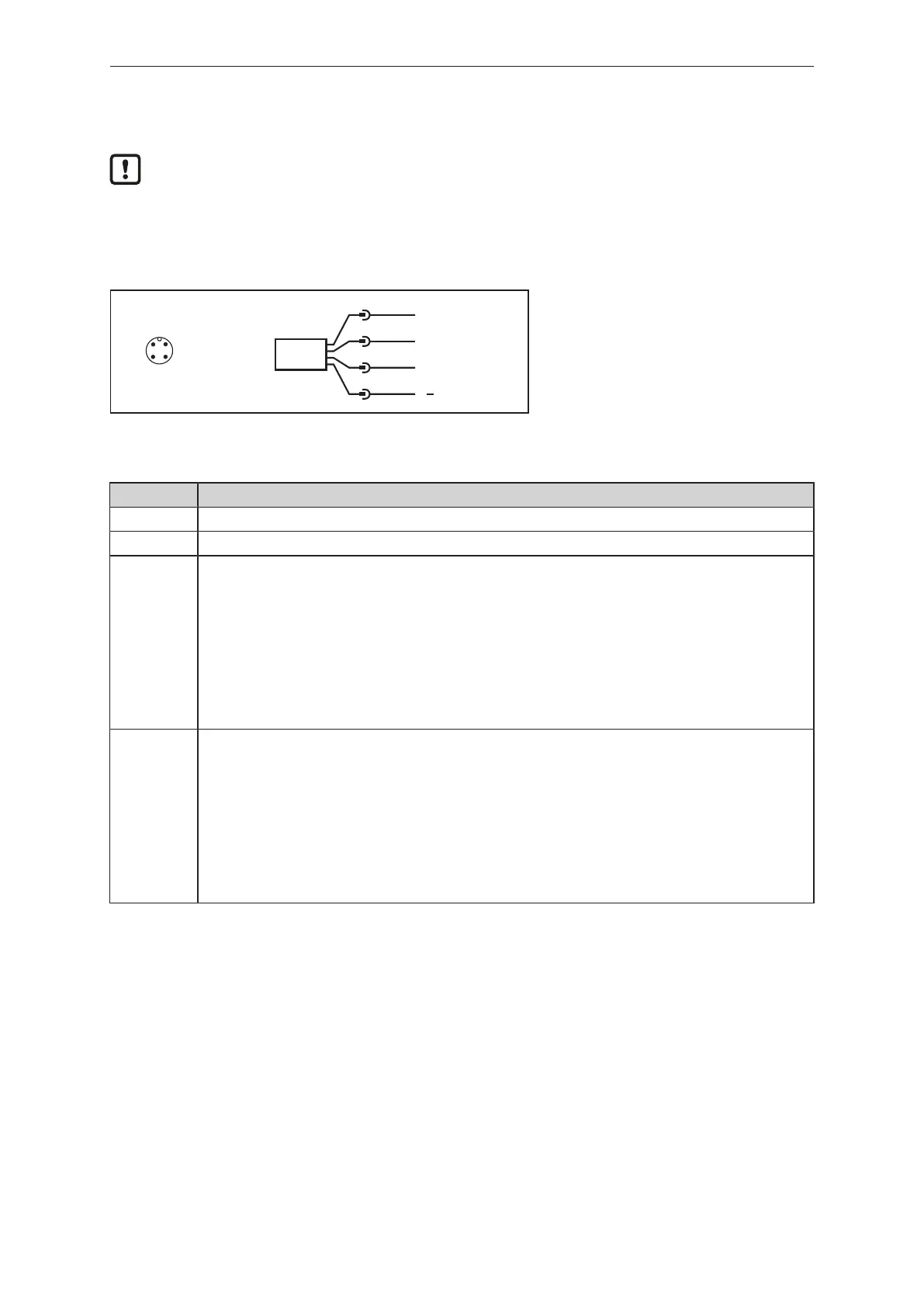
u Connect the unit as follows:
L
1 BN
2 WH
4 BK
3 BU
OUT1/IO-Link
OUT2
L+
43
2 1
Fig.4: Wiring diagram (colours to DINEN60947-5-2)
BK: black BN: brown
BU: blue WH: white
Pin Connection
1 L+
3 L-
4 (OUT1) • Switching signal flow
• Switching signal temperature
• Switching signal diagnosis
• Switching signal totaliser
• Pulse signal totaliser
• Frequency signal flow
• Frequency signal temperature
• IO-Link
• OFF (output switched to high impedance)
2 (OUT2/InD) • Switching signal flow
• Switching signal temperature
• Switching signal diagnosis
• Switching signal totaliser
• Pulse signal totaliser
• Analogue signal flow
• Analogue signal temperature
• Input for external totaliser reset
• OFF (output switched to high impedance)