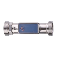
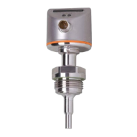
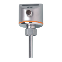
SU2020 SU8020 SU2021 SU8021 SU2621 SU8621 Ultrasonic flow meter
22
9 Set-up
After power on and expiry of the power-on delay time, the unit is in the normal operating mode. It
carries out its measurement and evaluation functions and generates output signals according to the
set parameters.
During the power-on delay time the outputs are switched as programmed:
• ON with normally open function (Hno / Fno)
• OFF with normally closed function (Hnc / Fnc)
• ON for detection of direction (dir.F)
• OFF for frequency output (FRQ)
• OFF for consumed quantity monitoring (ImP)
• 20 mA for analogue output (I)
9.1 Guided installation via an installation wizard
When changing from the process value display to the main menu via the [●] key for the first time, you
are asked whether you want a guided installation.
u Select [Yes] or [No].
w If [Yes] is selected, parameters, questions and instructions appear in succession. Use the [▲] and
[▼] keys to choose from the available options and the [●] key to confirm your selection.
w If [No] is selected, the main menu appears and the sensor functions according to the factory
settings. If necessary, change the factory settings. Ò See chapter Parameter setting.
The guided installation can be called up again at any time via the parameter [EF] > [CFG] >
[Guide].
During guided installation, the following setting options appear in succession:
1. [diS.R]: display rotation
2. [LanG]: display language
3. [Fdir]: flow direction
4. Output OUT1:
– [SEL1]: process value (flow or temperature) or diagnosis (flow direction or signal quality).
– [uni.T] / [uni.F]: standard unit of measurement
– [ou1]: switching signal (Hno, Hnc, Fno, Fnc), pulse signal/switching signal totaliser, frequency
signal
– configuration of the parameters according to the function selected for [ou1]:
limit values for switching signal: SP1, rP1, FH1, FL1
pulse value for totaliser: ImPS
switch point and reset for totaliser: ImPS1, rTo1
limit values for frequency signal: FSP1 (only for temperature), FEP1, FrP1
– [FOU1]: error behaviour of the output
5. Output OUT2:
– [SEL2]: process value (flow or temperature) or diagnosis (flow direction or signal quality).
– [uni.T] / [uni.F]: standard unit of measurement
– [ou2]: switching signal (Hno, Hnc, Fno, Fnc), pulse signal/switching signal totaliser, analogue
signal