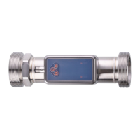
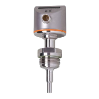
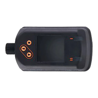
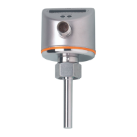
Ultrasonic flow meter SU2020 SU8020 SU2021 SU8021 SU2621 SU8621
21
Parameter Explanation
FOUx Behaviour of output OUTx in case of an error
FProx Counting method of the totaliser: consideration of the direction of flow
FrPx Frequency signal that is output when the upper measured value (MEW or FEPx) is reached.
FSPx Frequency start point for OUTx = Lower measured value from which a frequency signal is output
(only for temperature measurement).
Guide Activation of the guided installation (wizard)
ImPRx Totaliser function: pulse signal (ImPR = YES) or switching signal (ImPR = NO)
ImPSx Pulse value (= flow value at which 1 pulse is provided)
LanG Language selection for the display
LED.M Setting of the operating status LED
LFC Low flow cut-off (= flow value below which flow is evaluated as standstill)
oux Output configuration for output OUTx (e.g. switching output with hysteresis function)
P-n Output polarity for the switching outputs
rES Reset to factory settings (Back to Box) or reset of parameter settings (application reset).
rPx Reset point for switching output OUTx with hysteresis function
rTo Setting of the totaliser reset (manually or time-controlled)
S.FLW Simulated flow value in simulation mode
Sig.Q Switching signal for signal quality monitoring
S.On Starts the simulation mode
S.Tim Duration of the simulation in minutes
S.TMP Simulated temperature value in simulation mode
SELx Process value for output OUTx
SPx Switch point for switching output OUTx with hysteresis function
uni.F Standard unit of measurement for flow
uni.T Standard unit of measurement for temperature
Vol.L Current counter reading for totaliser Vol.L over the whole lifetime
Vol.x Current counter reading for totaliser Vol.x
 Loading...