1.8-4
GENERATOR OUTPUT LEVEL CALIBRATION
PREREQUISITES:
1-8-1 POWER
SUPPLY CALIBRATION
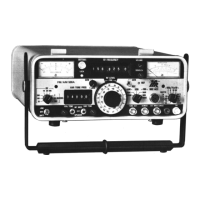
EQUIPMENT REOUIRED: 1 MEASURING
RECEIVER
FIGURES:
NONE
STEP PROCEDURE
1.
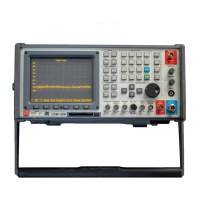
Apply Power
to COM-1208.
Allow
5
minute warm-up
period.
2. Press
GEN
Test
Mode Key
(3)
to access
RF
Generate Operation Screen.
3. Set
RF Field
to
405.5000
MHz.
4.
Set all Modulation
Sources to OFF.
5. Set Output to
T/H
and connect Measuring Receiver
to
T/R
Connector.
Set
Measuring
Receiver for Automatic Tuning
and
Tuned RF Level Measurement.
6. Set Output
Level
to
-20
dBm. Verify Measuring Receiver reads
-20
dBm
(t2
dB).
lf not,
go
to Step
14.
7.
Set Output Level
to
-9O
dBm.
Verify Measuring
Receiver
reads -90
dBm
(t2
dB). lf not,
go
to Step
14.
8. Set
Output
Level
to
-130
dBm.
Verify
Measuring Receiver reads
-130
dBm
(12.5
dB). lf
not,
go
to Step
14.
9.
Set Output to
AUX
and connect Measuring Receiver
to
AUX RF
OUT Connector
(13).
10.
Set Output
Level
to
-20
dBm.
Verify Measuring Receiver reads
-20
dBm
(12
dB).
lf not,
go
to Step
14.
11.
Set Output Level
to
-9O
dBm.
Verify
Measuring Receiver reads
-90
dBm
(t2
dB).
lf
not,
go
to Step
14.
12.
Set Output
Level
to
-130
dBm. Verify Measuring Receiver reads
-130
dBm
(42.5
dB).
lf
not,
go
to Step 14.
13.
Set COM-120B
to OFF and disconnect
test equipment.
PERFORM THE FOLLOWING
ONLY
WHEN REOUIRED.
14. Press
SETUP MEMORY Key
(21).
15.
Select
"1.
Calibration"
f rom
Setup
Screen.
16. Press
ENTER Key
to access Password Field. Press
SHIFT,
F, M, Y,
S,
V,
C,
D and
SHIFT
Data Entry Keys
(5).
Press
ENTER Key.
17.
Select
"6.
RF
GENERATOR
-
OUTPUT
LEVEL"
to access
RF
GENERATOR
LEVEL
CALIBRATION
Screen.
1-11
1-8-4
GENERATOR
OUTPUT
LEVEL
CALIBRATION
PREREQUISITES:
1-8-1
POWER
SUPPLY
CALIBRATION
EQUIPMENT
REQUIRED:
1
MEASURING
RECEIVER
FIGURES:
NONE
STEP
PROCEDURE
1.
Apply
Power
to
COM-120B.
Allow
5
minute
warm-up
period.
2.
Press
GEN
Test
Mode
Key
(3)
to
access
RF
Generate
Operation
Screen.
3.
Set
RF
Field
to
405.5000
MHz.
4.
Set
all
Modulation
Sources
to
OFF.
5.
Set
Output
to
TIR
and
connect
Measuring
Receiver
to
T/R
Connector.
Set
Measuring
Receiver
for
Automatic
Tuning
and
Tuned
RF
Level
Measurement.
6.
Set
Output
Level
to
-20
dBm.
Verify
Measuring
Receiver
reads
-20
dBm
(±2
dB).
If
not,
go
to
Step
14.
7.
Set
Output
Level
to
-90
dBm.
Verify
Measuring
Receiver
reads
-90
dBm
(±2
dB).
If
not,
go
to
Step
14.
8.
Set
Output
Level
to
-130
dBm.
Verify
Measuring
Receiver
reads
-130
dBm
(±2.5
dB).
If
not,
go
to
Step
14.
9.
Set
Output
to
AUX
and
connect
Measuring
Receiver
to
AUX
RF
OUT
Connector
(13).
10.
Set
Output
Level
to
-20
dBm.
Verify
Measuring
Receiver
reads
-20
dBm
(±2
dB).
If
not,
go
to
Step
14.
11.
Set
Output
Level
to
-90
dBm.
Verify
Measuring
Receiver
reads
-90
dBm
(±2
dB).
If
not,
go
to
Step
14.
12.
Set
Output
Level
to
-130
dBm.
Verify
Measuring
Receiver
reads
-130
dBm
(±2.5
dB).
If
not,
go
to
Step
14.
13.
Set
COM-120B
to
OFF
and
disconnect
test
equipment.
PERFORM
THE
FOLLOWING
ONLY
WHEN
REQUIRED.
14.
Press
SETUP
MEMORY
Key
(21).
15.
Select
"1.
Calibration"
from
Setup
Screen.
16.
Press
ENTER
Key
to
access
Password
Field.
Press
SHIFT,
F, M, Y,
S,
V, C, D
and
SHIFT
Data
Entry
Keys
(5).
Press
ENTER
Key.
17.
Select
"6.
RF
GENERATOR
-
OUTPUT
LEVEL"
to
access
RF
GENERATOR
LEVEL
CALIBRATION
Screen.
1 -11
Scans by ArtekMedia © 2008