1-8-15
AM MODULATION
METER
CALIBRATION
PREREQUISITES:
1-8-1 POwER
SUPPLY CALIBRATION
1-8-2 TCXO/OCXO
CALIBRATION
EQUIPMENT REOUIRED: 1 MODULATION ANALYZER
1
SIGNAL GENERATOR
FIGURES:
1-9
STEP PROCEDURE
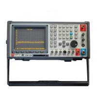
1. Apply Power
to COM-1208. Allow
5
minute warm-up
period.
2. Press REC Test Mode Key
(3)
to access
RF Receive
Operation
Screen.
3. Set Receive
Operation Screen
Parameters
as
follows:
RF Field
101 MHz
lnput
ANT
Attenuation
30 dB
Demodulation
Type AM
lF Bandwidth
300
kHz
4. Move
cursor to Line.
Press
CONFIG Soft
Function Key F6
to
access
Receiver Audio/Data
Filters
Setup
Menu.
Set
Modulation Meters Filter Line
High-Pass Filter for
300
Hz.
Set
Modulation
Meters Filter Line Low-Pass Filter for 4
kHz.
Press
EXEC
Soft
Function Key
F5. Press
RETURN
Soft
Function
Key
F6
to
return
to
RF Receive
Operation Screen.
5.
Connect
Test Equipment
as shown
in
Figure 1-9.
6.
Access Full
Screen
Modulation
Meter.
7.
Set
AM
Modulation Meter Parameters
as
follows:
Range 100%
Peak Hold
OFF
Average
OFF
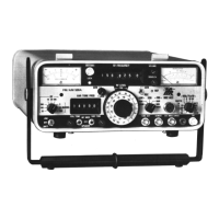
8. Set Signal
Generator
for 101 MHz
Signal
AM Modulated with 1
kHz
tone at
70% Modulation
at
-10
dBm
output
level.
9.
Set
Modulation Analyzer lor
AM Measurement with
300
Hz High-Pass Filter,
3
kHz
Low-Pass Filter
and
Peak+
detector activated.
10. Verify
Modulation Analyzer reading
and AM Modulation Meter Reading match
(t5.1%).
lf
not,
go
to Step
12.
1 1.
Set COM-1208
power
to OFF and disconnect
test equipment.
PERFORM THE FOLLOWING
ONLY
WHEN REQUIRED.
12. Press
SETUP
MEMORY Key
(21).
13.
Select
"1.
Calibration"
f rom
Setup Screen.
1
-43
1-8-15
AM
MODULATION
METER
CALIBRATION
PREREQUISITES:
EQU
IPMENT
REQUIRED:
FIGURES:
STEP
1-8-1
POWER
SUPPLY
CALIBRATION
1-8-2
TCXO/OCXO
CALIBRATION
1
1
1-9
MODULATION
ANALYZER
SIGNAL
GENERATOR
PROCEDURE
1.
Apply
Power
to
COM-120B.
Allow
S
minute
warm-up
period.
2.
Press
REC
Test
Mode
Key
(3)
to
access
RF
Receive
Operation
Screen.
3.
Set
Receive
Operation
Screen
Parameters
as
follows:
RF
Field
Input
Attenuation
Demodulation
Type
IF
Bandwidth
101
MHz
ANT
30
dB
AM
300
kHz
4.
Move
cursor
to
Line.
Press
CONFIG
Soft
Function
Key
F6
to
access
Receiver
Audio/Data
Filters
Setup
Menu.
Set
Modulation
Meters
Filter
Line
High-Pass
Filter
for
300
Hz.
Set
Modulation
Meters
Filter
Line
Low-Pass
Filter
for
4
kHz.
Press
EXEC
Soft
Function
Key
FS.
Press
RETURN
Soft
Function
Key
F6
to
return
to
RF
Receive
Operation
Screen.
S.
Connect
Test
Equipment
as
shown
in
Figure
1-9.
6.
Access
Full
Screen
Modu
lation
Meter.
7.
Set
AM
Modulation
Meter
Parameters
as
follows:
Range
Peak
Hold
Average
100%
OFF
OFF
8.
Set
Signal
Generator
for
101
MHz
Signal
AM
Modulated
with
1
kHz
tone
at
70%
Modulation
at
-10
dBm
output
level.
9.
Set
Modulation
Analyzer
for
AM
Measurement
with
300
Hz
High-Pass
Filter,
3
kHz
Low-Pass
Filter
and
Peak+
detector
activated.
10.
Verify
Modulation
Analyzer
reading
and
AM
Modulation
Meter
Reading
match
(±S.1
%).
If
not,
go
to
Step
12.
11.
Set
COM-120B
power
to
OFF
and
disconnect
test
equipment.
PERFORM
THE
FOLLOWING
ONLY
WHEN
REQUIRED.
12.
Press
SETUP
MEMORY
Key
(21).
13.
Select
"1.
Calibration"
from
Setup
Screen.
1-43
Scans by ArtekMedia © 2008