Do you have a question about the Igema DLT2 and is the answer not in the manual?
Details symbols used for safety warnings in the manual, including danger, caution, and info.
Specifies the device's intended application for indicating fill levels in containers and compliance with directives.
Covers essential safety precautions for installation, maintenance, and handling equipment, including PPE and load handling.
Provides guidance on handling the device during transport, storage, servicing, and returning goods, emphasizing safety.
States IGEMA GmbH's disclaimer of liability for non-compliance with safety regulations and unauthorized modifications.
Explains the capacitive fill level measurement method using the EC 8 probe and the DLT2/DLT3 evaluation.
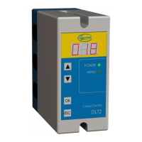
Details the DLT2/DLT3 control unit features, including display, LEDs, buttons, and operational indicators.
Describes error codes displayed on the 7-segment display, relay behavior, and current output during errors.
Provides technical drawings and descriptions of the device's physical dimensions and mounting features.
Details methods for installing the device using a spring catch or screw fixing on a mounting plate.
Covers critical electrical connection safety precautions, including mains protection and inductive consumer considerations.
Illustrates the system setup including the steam boiler, probe, and evaluation device with a schematic diagram.
Shows the terminal assignments for the DLT2/DLT3 evaluator, including power, relay, and probe connections.
Specifies the required cable type and connection layout for linking the evaluator to the probe.
Explains how to connect the probe, which features a 4-pole plug connector, to the evaluator via the cable.
Details the requirements for the 4 mA .. 20 mA power interface, including cable type and maximum load.
Outlines the two-level menu structure and navigation principles for the DLT2/DLT3 configuration.
Presents a menu diagram showing the structure and options available for device configuration.
Explains the procedure for entering numerical values using the device's control buttons and display.
Provides a step-by-step example of how to enter the device password for accessing configuration settings.
Guides users on setting the minimum and maximum fill levels in the boiler for device calibration.
Details the configuration steps for activating and setting the overfill protection and return levels on the DLT3.
Lists technical specifications including manufacturing standards, supply voltage, power consumption, and protection class.
Specifies the maximum output current, load, switching voltage, and switching current for the device outputs.
Provides information found on the device's data plate, including model type, voltage, and environmental ratings.
Lists common error codes for the evaluation device, their causes, and suggested remedial actions like replacing the device.
Details error codes related to the probe, including hardware faults, calibration issues, and connection problems.
| Brand | Igema |
|---|---|
| Model | DLT2 |
| Category | Transmitter |
| Language | English |