11
4.3 Error messages
In the 7-segment display, errors of the evaluator and probe are shown flashing, number-coded
and 3-digit.
In the event of any error, the relay (contacts 3, 4, 5) goes into the safe, currentless state
(contacts 3 - 4 closed) (see 5.3.2). The current output can be routed via this or an error
signal can be connected.
In the event of an error, the 4 mA .. 20 mA output jumps to 0 mA within less than 3 s
For analysis and troubleshooting see Chap. 8.
5. Assembly and Installation
The device is supplied in a plastic plug-in housing for fitting into switch cabinets. The housing
is designed for quick fitting with a spring catch for the DIN EN 50022 standard 35 mm carrier
rail and for screw fixing on a mounting plate.
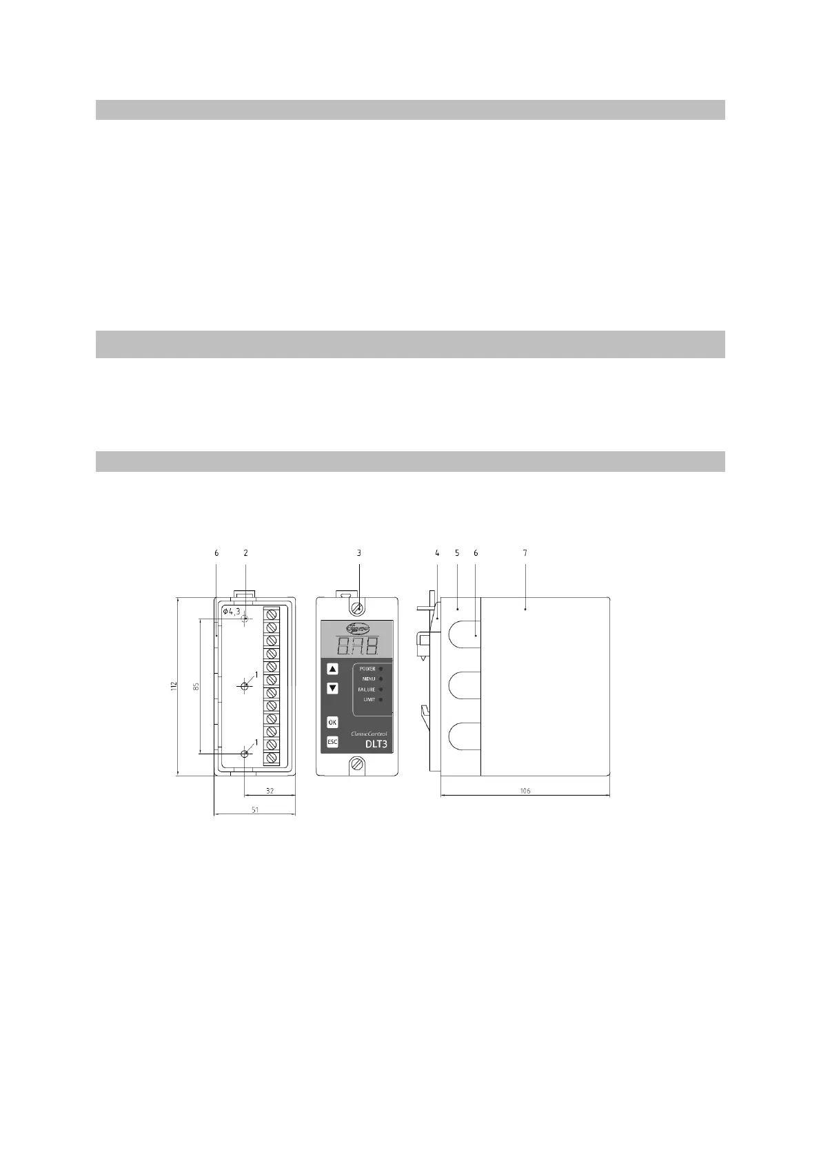
5.1 Installation dimensions and descriptions
Base Front view Side view
with connecting terminals
1 Screws for quick fastening with spring catch
2 Holes, ø 4.3 mm
3 Fixing screws
4 Quick fastening with spring catch
5 Base
6 Cable feedthrough
7 Hood