10
DLT3:
An overfill protection can be activated. Then a fill-level-limit (e.g. 70%) and a value for the
return to normal operation (e.g. 65%) must be programmed.
The controller supplies the level probe, which can be fitted in the boiler, and evaluates its
signal.
It is expected that because of the non-linear boiler geometry the fill level
(water quantity / volume) does not behave in a linear way to the fill depth
/ fill level!
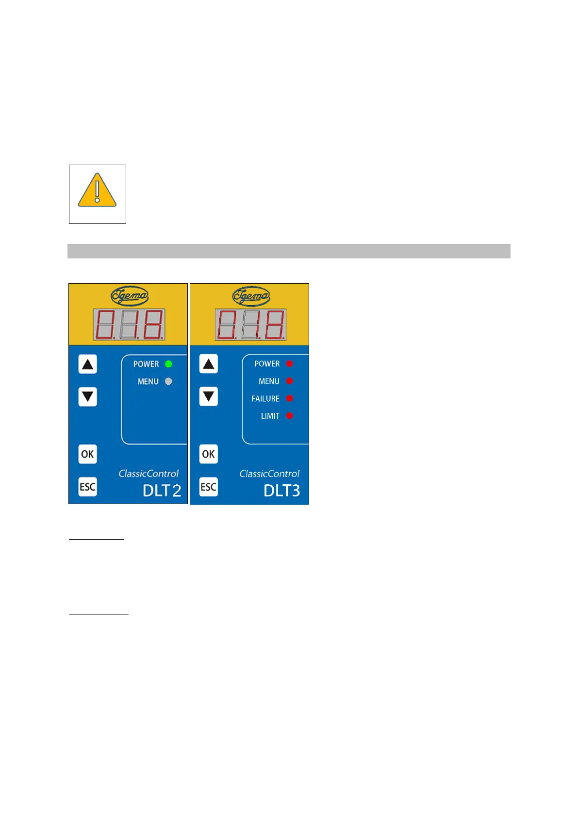
4.2 Control unit
• Seven segment display;
• 4 control LEDs, arranged on the right
vertically;
• 4 control buttons, arranged on the left
vertically;
At DLT2 + 3:
LED 1 (green) POWER flashes if power supply of controller or -
probe is faulty
LED 2 (yellow) MENU flashes in menu mode
Only at DLT3:
LED 3 (rot) FAILURE lights up if the device detects an electronics failure
LED 4 (grün) LIMIT lights up if overfill level is exceeded
When the controller and the probe are working correctly, the fill level in % of the range set appears in
the display: e.g. 018 (18%).
Fill levels above the two calibration points (0% and 100%) are still displayed in certain limits. The
4 mA .. 20 mA output follows the fill level / display, however only up to a value of 2.4 mA or 21.5 mA.
Further out of range values are no longer represented.