en
15
User manual Costawww.igloo.pl
9
3
7
2
1
3
4
5
5
6
7
89
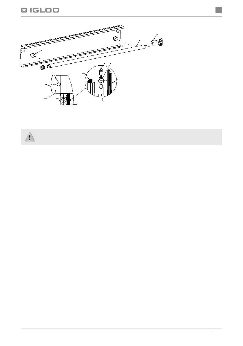
Fig.9 Exchange of the
fl uorescent lamps
6. SERVICE
6.1. Fault identifi cation and repair
In case of any diffi culties during actuation of the device or during its exploitation, please return to these chapters in this ma-
nual, which explain the performed operation. This aims to ensure that the device is properly operated. If you still experience
diffi culties, the following hints will help you solve the problem.
The device is not working... – Make sure that:
• The device is connected to the supply network
• Voltage and frequency in the network are compliant with those recommended by the producer 230V/50Hz
• The main switch is turned on
• Thermostat is switched on (Concerns the Igloo thermostat – If only two dots are displayed on the screen – turn on
the thermostat)
The device is operating, the lighting is switched off... – Make sure that:
• The lighting switch is on
• Fluorescent lamp or the starter of the device are not burnt
The device does not reach the proper temperature, the lighting is on...– Make sure that:
• The main switch is on
• Temperature setting on the thermostat is properly set
• The thermostat is operating properly
• Ambient temperature does not exceed 25ºC
• Enough time has passed for products to be cooled
• Ventilation holes of the device are not blocked
(This concerns the “IGLOO” thermostat) thermostat displays C0 or C1 or C2 instead of displaying tempera-
ture:
This situation shall occur, when one of temperature regulation sensors has been destroyed. The following
messages may be displayed in such case:
• C0 – temperature sensors inside the chamber are damaged – call authorized service
• C1 – failure of evaporator sensor - call authorized service
• C2 – failure of condenser alarm sensors (or failure of second evaporator sensor) – call authorized service
During maintenance services it is necessary to pay attention not to damage the data plate of the device Fig.10 (p.16),
which contains signifi cant information for servicing organs and waste removal companies.
1 – Plexi plate of the upper panel
2 – Grips fi xing the Plexi plate
3 – Grip of the fl uorescent lamp (the
upper panel)
4 – Glazed doors
5 – PVC profi le (side illumination)
6 – Transparent casing of the fl uore-
scent lamp (lampshade)
7 – Fluorescent lamp
8 – Casing of the fl uorescent lamp
9 – Starter of the fl uorescent lamp