12
STCS ed 07/02 CAESAR Star
Technical Documentation
Technical Documentation
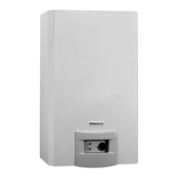
Electrical circuit.
The electrical circuit of the CAESAR Star appliance is
fully controlled by an electronic modulation board which
controls all generator functions and to which are
connected the electrical devices of the appliance.
230 V AC circuit.
Safety devices and controls.
Some of the control and safety devices operate at
mains voltage and others at low voltage.
Key:
B1 - D.h.w. NTC probe
B2 - Flow measurer
E1 - Igntion/detection glow electrode
E2 - Linit thermostat
E3 - Overheat.safety thermo
H1 - Flame presence LED
H2 - Fault indicator LED
Y1 - Gas valve
Y2 - Modulator coil
M1 - Fan
S1 - Natural/LPG gas switch
S3 - Fume pressure switch
S4 - Master switch (D.h.w. adjuster)
F - Fuse
This detects ignition of the burmer by whose flame it is invested.
It is connected to the ignition/detection circuit of the adjustment board.
The electrode also works as an ignition glow electrode.
Detection electrode
(E1)
This interrupts power to the circuit when power input is
over 2 A. It is fitted on the modulation board.
Fuse
Fuse 2 AF
250 V
When the safety temperature is exceeded (100 ºC) this
interrupts power to the main coils of the gas valve (Y1).
It is located at the exchanger outlet.
Overheating safety
thermostat
(E3)
Two-contact
clicson
thermostat
When the safety temperature is exceeded (85 ºC) this
interrupts power to the main coils of the gas valve (Y1).
It is located on the d.h.w. exit pipe.
D.h.w. limit thermostat
(E2)
Two-contact
clicson
thermostat
Blue
Brown
Yellow/green
White
White
Blue
Brown
Blue
Brown
Black
Red
Red
Black
Black
Black
Red
Black
Orange
F
S4
ON/OFF
D.H.W. Adjust.
Primary
Secondary
Antifreeze kit
power supply
230Vac
50HZ
power
supply